
Specifications


Page 33 /148
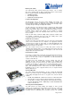
The MCS works with the Routing Engine to provide control and monitoring
functions for router components and to provide SONET clocking for the router.
The MCS installs into the midplane from the rear of the chassis.
The router can be equipped with up to two MCSs for redundancy. If two MCSs
are installed, one acts as the master MCS and the other acts as backup. If the
master MCS fails or is removed, the backup restarts and becomes the master
MCS.
Each MCS requires a Routing Engine to be installed in an adjacent slot. MCS0
installs above RE0, and MCS1 installs below RE1. Even if an MCS is physically
installed in the chassis, it does not function if no Routing Engine is present in the
adjacent slot.
The MCS performs the following functions:
§ Monitoring and control of router components—Monitors components for
failure and alarm conditions. The MCS collects statistics from all sensors
in the system and relays them to the Routing Engine, which generates
control messages or sets an alarm. The MCS relays control messages
from the Routing Engine to the router components.
§ Power-up and power-down of components—Controls the power-up
sequence of router components at startup, and powers down
components when their offline buttons are pressed.
§ Control of mastership—In a system with redundant Routing Engine,
MCS, or PCG modules, the MCS signals which of the modules is the
master and which is the backup.
§ Control of FPC resets—If the MCS detects errors in an FPC, it attempts
to reset the FPC. After three unsuccessful resets, the MCS takes the
FPC offline and informs the Routing Engine. Other FPCs are unaffected,
and normal system operation continues.
§ SONET clock source—The MCS generates the 19.44-MHz SONET
clock. Each MCS supplies the SONET clock signal, along with a signal
that indicates which MCS is the master SONET clock. Each MCS also
provides two BITS interfaces for synchronization of the SONET clocks to
an external reference source.
The MCS also monitors the SONET clock, the SONET reference clocks (from the
FPCs and the BITS interfaces) and the system clocks from the PCGs.
MCS Components
The MCS contains the following components:
§ PCI interface to the Routing Engine
§ 100-Mbps Ethernet switch for inter-module communication
§ 19.44-MHz stratum 3 reference clock for SONET PICs
§ Two BITS interfaces for external clock reference
§ I 2 C controller to monitor the status of router components
§ RS-232 debugging port
§ Three LEDs—One blue MASTER, one green OK, and one amber FAI L
§ Offline button for module removal
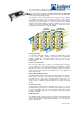
MCS LEDs
Three LEDs are located on the faceplate of the MCS.
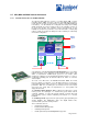
Craft Interface
The craft interface allows you to view status and troubleshooting information at a
glance and to perform many system control functions. The craft interface is
located on the front of the chassis above the FPC card cage and contains the
following elements :
§ Alarm LEDs and Alarm Cutoff Button
§ LCD Display and Navigation Buttons
§ Host Module LEDs
§ FPC LEDs and Offline Button
Connector Interface Panel (CIP)