
Specifications


Page 32 /148
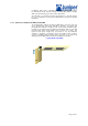
Each PCG contains the following components:
§ 125-MHz system clock generator
§ EEPROM—Stores the serial number and revision level of the PCG
§ Three LEDs—one blue MASTER, one green OK and one amber FAI L
§ Offline button for module removal
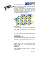
PCG LEDs
Three LEDs are located on the faceplate of the PCG. Table 6 describes the
functions of these LEDs.
Host Module
The host module provides the routing and system management functions of the
router. Additionally, the host module provides the SONET clock source for
SONET interfaces. The host module consists of the following components :
§ Routing Engine
§ Miscellaneous Control Subsystem (MCS)
The router can be equipped with one or two host modules. For each host module,
the Routing Engine and MCS function as a unit, each component requiring the
other to operate; if the adjacent component is not present, a Routing Engine or
MCS will not operate, even if physically installed in the router.
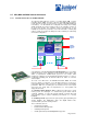
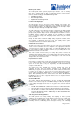
Routing Engine
The Routing Engine consists of an Intel-based PCI platform running JUNOS
Internet software. The Routing Engine maintains the routing tables used by the
router and controls the routing protocols that run on the router. The Routing
Engine installs into the center rear of the chassis. The Routing Engine is hot-
pluggable.
The router can be equipped with up to two Routing Engines for redundancy. If
two Routing Engines are installed, one acts as the master Routing Engine and
the other acts as backup. If the master Routing Engine fails or is removed, the
backup restarts and becomes the master Routing Engine.
Each Routing Engine requires an MCS to be installed in an adjacent slot. RE0
installs below MCS0, and RE1 installs above MCS1. Even if a Routing Engine is
physically installed in the chassis, it does not function if no MCS is present in the
adjacent slot.
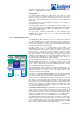
Routing Engine Components
The Routing Engine is a two-board system comprising the following components:
§ CPU—One 333-MHz mobile Pentium II processor with an integrated
256-KB Level 2 cache.
§ SDRAM—Three 168-pin DIMMs containing 768-MB ECC SDRAM,
which provides storage for the routing and forwarding tables and for
other Routing Engine processes.
§ 80- or 96-MB compact flash disk—Provides primary storage. It can hold
two software images, two configurations files, and microcode. This disk
is fixed and is not accessible from outside the router.
§ 6.4-GB IDE hard disk—Provides secondary storage for log files, memory
dumps, and rebooting the system in the event of a flash disk failure.
§ 110 MB PC card —Provides storage for software images for system
upgrades.
§ Out-of-band management access—One 10/100 Mbps Ethernet port
(with autosensing RJ-45 connector), and two RS-232 (DB9 connectors)
asynchronous serial ports, one console and one auxiliary, to connect to
a console, laptop or terminal server. The management access ports are
located on the CIP.
§ EEPROM—Stores the serial number of the Routing Engine.
§ Three LEDs—One green MASTER, one green ONLINE and one red
OFFLINE, which are located on the craft interface.
§ Reset button—On the Routing Engine faceplate.
Miscellaneous Control Subsystem (MCS)