
Specifications


Page 30 /148
§ Two Distributed Buffer Manager ASICs—One sends packets to the
output buffer and oneforwards notification to the I/O Manager ASICs on
the FPCs.
§ Internet Processor II ASIC—Performs route lookups.
§ 8-MB of parity-protected SSRAM.
§ Processor subsystem—Comprises one PowerPC603e processor, 256-
KB of parity-protected Level 2 cache, and 64-MB of parity-protected
DRAM. This subsystem handles exception packets and management of
the SFM.
§ EEPROM—Stores the serial number and revision level.
§ Two L EDs—One Green OK and one amber FAI L.
§ Offline button for module removal.
SFM LEDs
Each SFM has two LEDs that indicate its status.
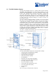
Flexible PIC Concentrators (FPCs)
The Flexible PIC Concentrators (FPCs) house the various PICs used in the
router. Up to eight FPCs install vertically into the midplane from the front of the
chassis. The FPCs are numbered left to right, from FPC0 to FPC7. Each FPC
has four connectors into which a PIC can be installed, allowing up to four PICs
per FPC. An FPC can be installed into any FPC slot, regardless of the PICs it
contains. If a slot is not occupied by an FPC, a blank FPC panel must be installed
to shield the empty slot and to allow cooling air to circulate properly through the
FPC card cage.
The FPCs connect the PICs to the rest of the router so that incoming packets can
be forwarded across the midplane to the appropriate destination port. FPCs
contain shared memory, which is managed by the Distributed Buffer Manager
ASIC on each SFM, for storing data packets received by the PICs. The I/O
Manager ASIC on each FPC divides incoming data packets from the PICs into
64-byte memory blocks, which are stored in a shared memory buffer, and
reassembles them into data packets when they are ready for transmission.
FPCs are hot-insertable and hot-removable. Removing an FPC causes a brief
interruption of forwarding performance (about 200 ms) as the Packet Forwarding
Engine flushes the memory pool.
When you install an FPC into an operating router, the Routing Engine downloads
the FPC software, the FPC runs its diagnostics, and the PICs on the FPC slot are
enabled. No interruption occurs to the routing functions.
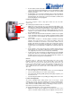
FPC Components
Each FPC contains the following components:
§ FPC card carrier—Contains the ASICs, connectors, and processor
subsystem.
§ Four I/O Manager ASICs—Parse Layer 2 and 3 data and perform
encapsulation and segmentation.
§ Two Packet Director ASICs—One distributes incoming packets to the
I/O Manager ASICs and the second directs outgoing packets from the
I/O Manager ASIC to the PICs.
§ Eight identical 32-MB SDRAM DIMMs —Form the shared memory buffer
for the system.
§ 1-MB parity-protected SSRAM—Stores data structures used by the I/O
Manager ASICs.
§ Processor subsystem—Comprises one PowerPC 603e-based CPU with
32 MB of parity-protected DRAM.
§ EEPROM—Stores the serial number and revision level of the FPC.
§ Two LEDs—One Green OK and one red FAI L, which are located on the
craft interface.
§ Offline button for module removal, located on the craft interface.
FPC LEDs
Each FPC has two LEDs that report its status. The LEDs are located above each
FPC, on thecraft interface.