
Specifications

Page 29 /148
the chassis, and the SFMs, Routing Engine, MCS, and PCGs install
horizontally from the rear of the chassis.
§ Switching and Forwarding Modules (SFMs)—From one to four SFMs
can be installed into the rear of the chassis.
§ Flexible PIC Concentrators (FPCs)—From one to eight FPCs can be
installed into the front of the chassis. Each FPC has a set of connectors
for attaching one or more PICs. The router supports two types of FPCs:
o FPC1—Supports lower-speed SONET OC-12 and Gigabit
Ethernet PICs
o FPC2—Supports higher-speed OC-48 and Tunnel PICs
§ Physical Interface Cards (PICs)—From one to four PICs can be installed
in each FPC. PICs provide support for various network media, including
OC-12 ATM, OC-12, OC-48 and OC-192 SDH/SONET, Channelized
OC-12, and Gigabit Ethernet.
§ PFE Clock Generators (PCGs)—Two PCGs are installed into the rear of
the chassis.
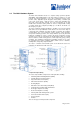
Midplane
The midplane is located in the center of the chassis and forms the rear of the
FPC card cage. The FPCs install into the midplane from the front of the chassis,
and the SFMs, Routing Engines, MCSs, and PCGs install into the midplane from
the rear of the chassis. The power supplies and cooling system components also
connect to the midplane. The midplane contains an EEPROM that stores the
serial number and revision level of the midplane.
The midplane performs the following major functions:
§ Transfer of data—Data packets are transferred across the midplane
from the FPCs to the SFMs, which perform their switching and
forwarding function, then transfer the packets back across the midplane
to the shared memory buffers on the FPCs.
§ Power distribution—The router power supplies are connected to the
midplane, which distributes power to all the router’s components.
§ Signal connectivity—The midplane provides signal connectivity to the
FPCs, SFMs, Routing Engines, and other system components for
monitoring and control of the system.
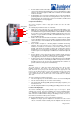
Switching and Forwarding Modules (SFMs)
The Switching and Forwarding Modules (SFMs) provide route lookup, filtering,
and switching to the destination FPC. Up to four interconnected SFMs can be
installed in the router, providing a total of 160 million packets per second (Mpps)
of forwarding. The SFMs provide the following functions:
§ Route lookups—The Internet Processor II ASIC on each SFM performs
route lookups using the forwarding table stored in the synchronous
SRAM (SSRAM).
§ Management of shared memory on the FPCs—One Distributed Buffer
Manager ASIC on each SFM uniformly allocates incoming data packets
throughout shared memory on the FPCs.
§ Transfer of outgoing data packets to the FPCs—A second Distributed
Buffer Manager ASIC on each SFM passes data packets to the FPCs for
reassembly when the data is ready to be transmitted.
§ Transfer of exception and control packets—The Internet Processor II
ASIC passes exception packets to the microprocessor on the SFM,
which processes almost all of them. The remainder are sent to the
Routing Engine for further processing. Any errors originating in the
Packet Forwarding Engine and detected by the SFMs are sent to the
Routing Engine using syslog messages.
The SFMs are hot-removable and hot-insertable. Inserting or removing an SFM
causes a brief interruption in forwarding performance (about 500 ms) as the
Packet Forwarding Engine reconfigures the distribution of packets across the
remaining SFMs.
SFM Components
The SFM is a two-board system comprising the following components: