
Specifications

Page 28 /148
§ Hot-insertable and hot-removable—You can remove and replace these
components without powering down the router or disrupting the routing
functions. The power supplies, SFMs, PICs and FPCs are hot-insertable
and hot-removable.
§ Hot-pluggable—You can remove and replace these components without
powering down the router, but the routing functions of the system are
interrupted when the component is removed. The PCGs, the MCS, and
the Routing Engine are hot-pluggable.
Component Redundancy
The router is designed so that no single point of failure can cause the entire
system to fail.
The following major hardware modules are redundant:
§ SFMs —The router can have up to four interconnected SFMs. If one
SFM fails, the switching and forwarding functions of the failed module
are distributed among the remaining SFMs. Total bandwidth is reduced
by 1/n, where n is the total number of SFMs installed in the router. For
example, in a system with four SFMs, each SFM handles 25 percent of
the forwarding capacity.
§ PCGs—The router has two PCGs. Both PCGs send their clock signals
to the forwarding components, along with a signal that indicates which
clock is the master. If one PCG fails, the other PCG becomes the master
system clock.
§ Host module—Comprises a Routing Engine and MCS functioning
together. The router can have one or two host modules. If two host
modules are installed, one functions as the master and the other as
backup. If the master host module (or either of its components) fails, the
backup takes over as the master host module. To operate, each host
module requires a Routing Engine and MCS to be installed in adjacent
slots.
§ Power supplies—The router has two power supplies, which share the
load evenly. If one of the power supplies fails, the second power supply
can supply full power to the router’s components indefinitely.
§ Cooling system—The front and rear cooling subsystems have redundant
components, which are controlled by the MCS. If an impeller or fan fails,
the MCS increases the speed of the remaining impellers and fans to
provide sufficient cooling for the unit indefinitely.
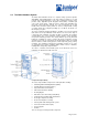
Chassis
The router chassis is a rigid sheet metal structure that houses all the router
hardware components. The chassis is 35 in. (89 cm) high, 17.5 in. (44.4 cm)
wide, and 29 in. (73 cm) deep. At its widest point—the front support posts—the
router is 19.2 in. (48.8 cm) wide. It is 19 in. (48.3 cm) wide to the tips of the center
rack-mounting ears. The chassis installs into standard 19 in. equipment racks or
Telco center-mounted racks, and two routers can be installed into one standard,
78-in. rack.
The chassis includes the following components:
§ Two front support posts used to bolt the chassis to a front-mounting rack
§ Two 19” rack-mounting ears for center rack mounting
§ Two electrostatic discharge (ESD) points (banana plug receptacles), one
front and one rear
§ Two internally threaded inserts providing grounding points for the router.
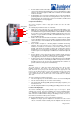
Packet Forwarding Engine
The Packet Forwarding Engine (PFE) provides Layer 2 and Layer 3 packet
switching, route lookups, and packet forwarding. The Packet Forwarding Engine
uses application-specific integrated circuits (ASICs) to perform these functions.
ASICs include the Distributed Buffer Manager, I/O Manager, Internet Processor II,
Packet Director, and various media-specific controllers.
The Packet Forwarding Engine consists of the follow ing components:
§ Midplane—A single, passive midplane is located in the center of the
chassis. The FPCs install vertically into the midplane from the front of
PCG
MCS
MCS
Routing Engines
Power Suplies
SFMSFM
SFMSFM