
Specifications

Page 26 /148
through vents located in the upper impeller tray. The air is channelled past the
Packet Forwarding Engine components, keeping them cool.
During normal operation, both pairs of impellers function at less than full capacity.
A temperature sensor on the backplane controls the speed of the impellers. If you
remove one impeller tray, the temperature of the backplane increases and the
speed of the remaining pair of impellers adjusts automatically to keep the
temperature within the acceptable range.
Impeller trays are field-replaceable, hot-insertable, and hot-removable. The upper
and lower impeller trays are not interchangeable.
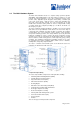
Triple Fan Assemblies
Three fan assemblies cool the Routing Engine and backplane. The fan
assemblies are located above the Routing Engine near the upper rear of the
chassis. They operate in unison to maintain an acceptable operating temperature
for the Routing Engine and backplane. The fans blow air out the exhaust vent at
the rear of the chassis, drawing air in through an air filter that covers the air intake
vent. The air is channeled past the rear of the backplane and around the Routing
Engine.
The fans are load-sharing. If one fan is removed or fails, the other two fans can
assume the full load. The backplane temperature sensor detects temperatures
above the acceptable range. Fan failure or an excessive temperature condition
triggers alarm LEDs on the craft interface and activates alarm relay contacts.
Each fan is field-replaceable, hot-insertable, and hot-removable.
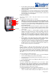
Power Supply Integrated Fan
Each power supply has its own integrated fan, which is used exclusively to cool
the power supply. The fan blows air out the exhaust vent at the rear of the
chassis, drawing air in through an air filter that covers the air intake vent at the
front of the chassis.