
Specifications

Page 25 /148
§ Alarm mode—Displays alarm conditions whenever the red or yellow
alarm LED is lit.
Alarm Relay Contacts
The craft interface contains two sets of relay contacts for alarms. You can cable
the alarm relay contacts to an external alarm device. Whenever a system
condition triggers either the red or yellow alarm on the craft interface, the alarm
relay contacts also are activated.
Routing Engine Ports
The Routing Engine has three ports for connecting external management
devices. You can use the command-line interface (CLI) on these management
devices to configure the router. These ports are located at the lower right corner
of the craft interface:
§ Console port—Used to connect a system console to the Routing Engine
with an RS-232 serial cable.
§ Auxiliary port—Used to connect a laptop or modem to the Routing
Engine with an RS-232 serial cable.
§ Ethernet management port—Used to connect the Routing Engine to a
management LAN (or any other device that plugs into an Ethernet
connection) for out-of-band management of the M40 router system. The
Ethernet port can be 10 or 100 Mbps and uses an autosensing RJ-45
connector.
Power Supplies
There are two fully redundant power supplies. A single power supply can provide
full power (up to 1500 watts) for as long as the system is operational.
Redundency is necessary only in case of power supply failure. At the instant that
power is cut off to one power supply, the other power supply automatically
assumes the entire electrical load. Each power supply has a system ground
connector.
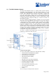
The power supplies install at the lower rear of the chassis, in the power supply
bays. The power supplies are internally connected to the backplane, which
distributes the different output voltages produced by the power supplies
throughout the system and its components, depending on their voltage
requirements. Each power supply contains an integrated fan that cools the power
assembly. The complete power supply is field-replaceable.
The router supports two types of modular power supplies, AC and DC. Both types
are field-replaceable and hot-removable and hot-insertable. Each power supply
has a handle for removing the unit from the power supply bay. Both types have a
safety interlock lever that prevents the unit from being removed until the power is
cut off.
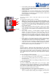
Power Supply LEDs
Two LEDs on each power supply faceplate report power supply status. In
addition, a fail condition triggers the red alarm LED on the craft interface. Table 7
describes the power supply LEDs.
Cooling System
The M40 router cooling system consists of three separate subsystems :
§ Impellers—Two pairs of redundant impellers cool the Packet Forwarding
Engine.
§ Triple Fan Assemblies—Three load-sharing fans cool the backplane and
the Routing Engine.
§ Power Supply Integrated Fan—A built-in fan cools each power supply.
Each cooling subsystem maintains a separate air flow, and each is monitored
independently for temperature control.
An air filter at the lower front of the chassis covers all three air intakes.
Impellers
The router is equipped with two redundant pairs of impellers to cool the Packet
Forwarding Engine components (that is, the backplane, SCB, FPCs, and PICs).
As the impellers draw air into the front of the card cage through an air filter that
covers the air intake vent, they force the exhaust from the rear of the chassis