
Specifications


Page 24 /148
Routing Engine downloads the FPC software, the FPC runs its diagnostics, and
the PICs on the FPC slot are enabled. Routing functions continue uninterrupted.
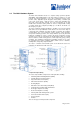
FPC Components
Each FPC contains the following components:
§ FPC board carrier with a PowerPC 603e processor and an I/O Manager
ASIC
§ Two identical 64-MB SDRAM DIMMs, used as shared memory by the
Distributed Buffer Manager ASIC on the backplane
§ 1-MB SSRAM
§ 8-MB DRAM, used by the 603e processor
§ EEPROM containing the FPC’s serial number and board release version
FPC LEDs
Each FPC has two LEDs that report its status. The LEDs are located below each
FPC, on the craft interface.
Physical Interface Cards (PICs)
PICs provide the physical connection to various network media types. Up to four
PICs can be installed into slots on each FPC. PICs receive incoming packets
from the network and transmit outgoing packets to the network. During this
process, each PIC performs framing and line-speed signaling for its media type.
Before transmitting outgoing data packets, the PICs encapsulate the packets
received from the FPCs. Each PIC is equipped with a media-specific ASIC that
performs control functions tailored to the PIC’s media type.
PICs are field-replaceable. To remove a PIC, you first remove its host FPC, which
is hot-removable and hot-insertable.
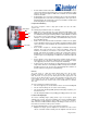
PIC LEDs
Each port on each PIC has one LED, located on the PIC faceplate above the
transceiver. Each LED has four different states, which are described in Table 3. If
the FPC that houses the PIC detects a PIC failure, the FPC informs the SCB,
which in turn sends an alarm to the Routing Engine.
Craft Interface
The craft interface allows you to view status and troubleshooting information at a
glance and to perform many system control functions. Located on the lower
impeller tray on the front of the chassis, the craft interface contains the following
elements :
§ System LEDs and Buttons
§ LCD Screen
§ Alarm Relay Contacts
§ Routing Engine Ports
System LEDs and Buttons
The system LEDs on the craft interface report the status of the Routing Engine,
the status of each FPC, and general system alarm conditions. The system
buttons on the craft interface allow you to reset clocks or stop alarms. The
following system LEDs and buttons are located on the craft interface :
§ FPC LEDs—Two LEDs (one green OK and one red Fail) indicate the
status of each FPC. The two LEDs and an offline button are located
below each FPC module slot.
§ Alarm LEDs—One large red Alarm LED and one large amber Alarm
LED indicate two levels of alarm conditions. You use the alarm cutoff
button to turn off either alarm.
§ Routing Engine LEDs—A red Fail LED and a green OK LED indicate the
status of the Routing Engine.
LCD Screen
The craft interface has a four-line LCD screen that operates in one of two display
modes:
§ Idle mode—Default mode that displays the current system status.