
Specifications

Page 23 /148
a “high temp” alarm. If the sensor exceeds the second threshold, the
Routing Engine initiates a system shutdown.
§ Transfer of exception and control packets—The Internet Processor ASIC
on the SCB passes exception packets to a microprocessor on the SCB,
which processes almost all of them. The remainder are sent to the
Routing Engine for further processing. Any errors originating in the
Packet Forwarding Engine and detected by the SCB are sent to the
Routing Engine using SYSLOG messages.
§ Control of FPC resets—The SCB monitors the operation of the FPCs. If
it detects errors in an FPC, the SCB attempts to reset the FPC. After
three unsuccessful resets, the SCB takes the FPC offline and informs
the Routing Engine. Other FPCs are unaffected, and normal system
operation continues.
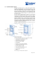
SCB Components
The SCB contains the following components:
§ Processing components
o PowerPC603e processor running at 200 MHz for handling
exception packets
o Internet Processor ASIC, which performs route lookups
o 33-MHz PCI bus, which connects the PowerPC603e processor
and the Internet Processor
§ Storage components
o Four slots of 1-MB to 4-MB SSRAM for the forwarding tables
that are associated with the ASICs
o 64-MB DRAM for the microkernel
o EEPROM containing the SCB’s serial number and board
release version
o 512-KB boot flash EPROM (programmable on the board)
§ System interfaces
o Two pai rs of L EDs
o 100-Mbps internal interface to the Routing Engine
o 8-bit parallel interface to the craft interface
o 9-port, 10-Mbps Ethernet internal hub interface to the FPC
boards (control path)
o RS-232 debugging port (DB-25 connector)
o 19.44-MHz reference clock (stratum 3) for SONET PICs
o I2C controller to read the I2C/EEPROMs in memory, FPCs,
backplane, and power supplies
SCB LEDs
Two pairs of circular LEDs are located on the front edge of the SCB.
Flexible PIC Concentrators (FPCs)
Flexible PIC Concentrators (FPCs) are the boards that hold the various media-
specific PICs used in the router. Up to eight FPCs install vertically into the
backplane from the front of the chassis, four on either side of the SCB. Any FPC
can be installed into any FPC slot. Each FPC has four connectors into which a
Physical Interface Card (PIC) can be installed, yielding up to four PICs per FPC.
The FPCs connect the PICs to the rest of the router so incoming packets can be
forwarded across the backplane to the appropriate destination port. FPCs contain
shared memory, which is managed by the Distributed Buffer Manager ASIC on
the backplane, for storing data packets received by the PICs. The I/O Manager
ASIC on each FPC breaks incoming data packets from the PICs into 64-byte
memory blocks, which are stored in a shared memory buffer. It then reassembles
them into data packets when they are ready for transmission.
FPCs are hot-insertable and hot-removable. Each FPC is mounted on a card
carrier. When you remove an FPC and install a new one, the backplane flushes
the entire system memory pool before the new card is brought online, a process
that takes about 200 ms. When you install an FPC into a running system, the