
Specifications

Page 22 /148
o Two asynchronous serial ports on the craft interface—Connect
a console, laptop, or modem for direct or local area network
management access to the M40 router.
o Ethernet port (10 or 100 Mbps, with an autosensing RJ-45
connector) on the craft interface—Connects the Routing Engine
to a terminal server or an SNMP management station for out-
of-band management of the M40 router.
o System LEDs on the craft interface—Green LEDs indicate OK
status and red LEDs indicate Fail status.
o LCD screen on the craft interface—Displays system status and
alarm information.
Packet Forwarding En gine
The Packet Forwarding Engine provides Layer 2 and Layer 3 packet switching,
route lookups, and packet forwarding. The Packet Forwarding Engine uses
application-specific integrated circuits (ASICs) to perform these functions. ASICs
include the Distributed Buffer Manager, I/O Manager, Internet Processor, and
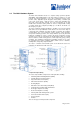
various media-specific controllers. The Packet Forwarding Engine occupies the
upper center front portion of the FPC card cage and consists of four components:
§ Backplane—A single backplane forms the rear of the FPC card cage.
The System Control Board (SCB) and up to eight Flexible PIC
Concentrators (FPCs) install vertically into the backplane from the front
of the chassis.
§ System Control Board (SCB)—The SCB installs vertically into the middle
slot of the backplane.
§ Flexible PIC Concentrators (FPCs)—Up to eight FPCs can be installed
into the backplane, four on either side of the SCB. Each FPC has a set
of connectors for attaching one or more Physical Interface Cards (PICs).
§ Physical Interface Cards (PICs)—One to four PICs can be attached to
each FPC. PICs provide support for various network media, such as
OC-12 ATM, OC-48 SONET, Ethernet, and DS3.
Backplane
The router backplane forms the back of the FPC card cage. The SCB and all the
FPCs install into the backplane from the front of the chassis. The backplane
contains a temperature sensor and is cooled by three fans operating in unison.
The backplane is a component of the Packet Forwarding Engine and performs
three major functions:
§ Power distribution and signal connectivity—The router power supplies
are connected to the backplane, which distributes power and provides
signal connectivity to all the FPCs, the SCB, and other system
components.
§ Management of shared memory on the FPCs—The Distributed Buffer
Manager ASIC on the backplane uniformly allocates incoming data
packets throughout shared memory on the FPCs.
§ Transfer of outgoing data cells to the FPCs—A second Distributed
Buffer Manager ASIC on the backplane passes data cells to the FPCs
for packet reassembly when the data is ready to be transmitted.
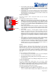
System Control Board (SCB)
The System Control Board (SCB) occupies the center slot of the card cage,
installing into the backplane from the front of the chassis. The SCB is a
component of the Packet Forwarding Engine and performs four major functions:
§ Route lookups—The Internet Processor ASIC on the SCB performs
route lookups using the forwarding table stored in the synchronous
SRAM (SSRAM). After performing the lookup, the Internet Processor
informs the backplane of the forwarding decision, and the backplane
forwards the decision on to the appropriate outgoing interface.
§ Monitoring of system components—The SCB monitors other system
components for failure and alarm conditions. It collects statistics from all
sensors in the system and relays them to the Routing Engine, which
sets the appropriate alarm. For example, if a temperature sensor
exceeds the first internally defined threshold, the Routing Engine issues