
Specifications

Page 19 /148
The Routing Engine LEDs on the craft interface report the status of the Routing
Engine. They are located above and below the Juniper Networks logo near the
middle of the craft interface.
Routing Engine Offline Buttons
Routing Engine offline buttons are used to take the Routing Engine offline in case
the Routing Engine needs to be replaced. The offline buttons are located to the
right of the Routing Engine. The Routing Engine LEDs are repeated on the
Routing Engine panel, which is located to the right of the Routing Engine on the
back of the chassis.
FPC LEDs
The FPC LEDs on the craft interface report the status of each FPC. They are
located on the right side the craft interface. Table 6 describes the FPC LEDs.
FPC Offline Buttons
FPC offline buttons are used to take the FPC offline if it needs to be replaced.
The offline buttons are located on the right side of the craft.
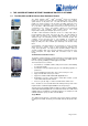
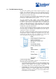
Power Supplies
The power supplies install at the lower rear of the chassis, in the power supply
bays. The power supplies are internally connected to the midplane, which
distributes the different output voltages produced by the power supplies
throughout the system and its components. The router has two fully redundant
power supplies that load-share during normal operation. A single power supply
can provide full power (up to 750 W) for as long as the system is operational.
Redundancy is necessary only in case of power supply failure. Each power
supply has an internal fan and is self-cooled.
Power supplies are field-replaceable. They are hot-removable and hot-insertable,
but you must turn off the power to the individual supply before removing it from
the chassis. When the power is cut off to one power supply or a failure occurs
within a power supply, the other power supply immediately and automatically
assumes the entire electrical load.
The router supports and AC power supplies. An enable control signal on the
output connector ensures that the power supply is fully seated into the router
midplane before the power supply can be turned on. The enable pin prevents a
user-accessible energy hazard, so there is no interlocking mechanism. The
enable pin disables the voltage at the output connector if the power supply is not
turned off before removal. Each power supply has status LEDs located below the
handle near the middle of the supply.
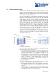
Cooling System
The router cooling system consists of the following components:
§ Three front fan trays —Cool the FPCs and the SSB. These fan trays are
located on the left front side of the chassis.
§ One rear fan tray—Cools the Routing Engine. This fan tray is located
immediately to the right of the Routing Engine
§ Power supply integrated fan—A built-in fan cools each power supply.
The four fan trays work together to provide side to side cooling. The fan trays
plug directly into the router midplane. Each front fan tray is a single field-
replaceable unit that contains three fans. The rear fan tray is a field-replaceable
unit that contains two fans. Both front and rear fan trays are hot-swappable.