
Specifications

Page 17 /148
o 33-MHz PCI bus—Connects system ASICs
§ Storage components
o Four slots of 1-MB RAM for forwarding tables associated with
ASICs
o 64-MB DRAM for the microkernel
o EEPROM containing the SSB’s serial number and board
release version
o 512-KB boot flash EPROM (programmable on the board)
§ System interfaces
o Three LEDs
o 100-Mbps Fast Ethernet link for internal interface to the Routing
Engine and FPC boards
o RS-232 debugging port (DB-25 connector)
o 19.44-MHz reference clock (stratum 3) for SONET PICs
o I2C controller to read the I2C/EEPROMs in memory, the FPCs,
the midplane, and the power supplies
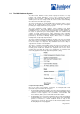
SSB LEDs
The SSB has two groups of LEDs, online/offline LEDs and status LEDs. The
online/offline LEDs indicate whether the SSB is online or offline. The status LEDs
indicate what type of task the SSB is performing.
Flexible PIC Concentrators (FPCs)
FPCs are the boards that hold the various media-specific PICs used in the router.
Up to four PICs can be installed on each FPC. FPCs install horizontally into the
midplane from the front of the chassis below the SSB. Any FPC can be installed
into any FPC slot. The FPCs are numbered 0 through 3, and the PFC slots are
labeled from top to bottom—FPC0, FPC1, FPC2, and FPC3. The FPCs connect
the PICs to the rest of the router so that incoming packets can be forwarded
across the midplane to the appropriate destination port. FPCs contain shared
memory, which is managed by the Distributed Buffer Manager ASIC on the SSB,
for storing data packets received by the PICs. The I/O Manager ASIC on each
FPC breaks incoming data packets from the PICs into 64-byte memory blocks,
which are stored in a shared memory buffer. It then reassembles them into data
packets when they are ready for transmission.
FPCs are hot-insertable and hot-removable. When you remove an FPC and
install a new one, the midplane flushes the entire system memory pool before the
new card is brought online, a process that takes about 200 ms. When you install
an FPC into a running system, the Routing Engine downloads the FPC software,
the FPC runs its diagnostics, and the PICs on the FPC slot are enabled. No
interruption occurs to the routing functions. If a slot is not occupied by an FPC, a
blank FPC carrier must be installed to shield the empty slot so that cooling air can
circulate properly throughout the FPC card cage.
FPC Components
§ Each FPC contains the following components:
§ FPC board carrier that has a PowerPC 603e processor and an I/O
Manager ASIC
§ Two identical 64-MB SDRAM DIMMs —Used as shared memory by the
Distributed Buffer Manager ASIC on the SSB
§ 1-MB SSRAM module
§ 8-MB DRAM—Used by the PowerPC 603e processor
§ EEPROM—Contains the FPC’s serial number and board release version
FPC LEDs
Each FPC has two LEDs that report its status. The LEDs are located on the craft
interface.
Physical Interface Cards (PICs)
Up to four PICs can be installed into slots on each FPC. PICs provide the
physical connection to various network media types. PICs receive incoming
packets from the network and transmit outgoing packets to the network. During
this process, each PIC performs framing and line-speed signaling for its media