
Specifications

Page 15 /148
§ Cooling system—The cooling subsys tems have redundant components,
which are controlled by the SSB. If a fan fails, the remaining fans
provide sufficient cooling for the unit indefinitely.
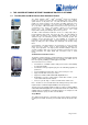
Chassis
The router chassis is a rigid sheet metal structure that houses all the other router
hardware components. The chassis is 14 in. (36 cm) high, 19 in. (48 cm) wide,
and 21 in. (54 cm) deep. The chassis has a mounting system that installs into
standard 19-in. equipment racks or Telco center-mounted racks and allows
multiple routers to be installed into one standard, 78-in.-high rack.
The chassis contains the following components:
§ Two electrostatic discharge points (banana plug receptacles), one front
and one rear
§ Front-mounting metal ears on either side, used to bolt the chassis to the
rack
§ Optional 19-in. rack-mounting ears for Telco center-rack mounting
§ Optional front-mounting brackets
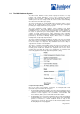
Routing Engine
The Routing Engine consists of an Intel-based PCI platform running JUNOS
Internet software. The Routing Engine module is located in the rear of the router
chassis, above the power supplies. It is housed in a metal case that is equipped
with thumbscrews to facilitate installation into and removal from the chassis. For
redundancy, you can have two Routing Engines in the router. If one Routing
Engine fails, the other one assumes the routing functions.
The Routing Engine is hot-pluggable. The Routing Engine LEDs are located on
the craft interface on the front of the router and are repeated on the Routing
Engine panel, which is part of the rear fan tray and is immediately to the right of
the Routing Engine. The Routing Engine module is a two-board subsystem
comprising the following components:
§ 333-MHz mobile Pentium II processor with a 512-KB cache CPU.
§ SDRAM—Three 168-pin DIMM sockets capable of holding up to 768 MB
of ECC SDRAM memory.
§ Management access—One 10/100 Mbps Ethernet port (with
autosensing RJ-45 connector) and two RS-232 (DB-9 connector)
asynchronous serial ports, one for the console and one auxiliary. These
ports are on the router’s craft interface.
§ 80-MB compact flash drive—Provides primary storage. It can hold two
software images, two configuration files, and microcode. This disk is
fixed and not accessible from the outside of the router.
§ 6.4-GB IDE hard disk drive—Provides secondary storage for logs,
recording entire memory dumps, and rebooting the system in event of a
flash disk failure.
§ Compact flash disk drive—Provides tertiary storage. It is accessible from
the outside of the router. You can use one type of PC card, a Sandisk
110-MB PCMCIA PC card.
§ EEPROM—Contains serial numbers, review level.
§ Hardware timer—Used for internal clocking.
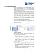
Packet Forwarding Engine
The Packet Forwarding Engine (PFE) provides Layer 2 and Layer 3 packet
switching, route lookups, and packet forwarding. The Packet Forwarding Engine
uses application-specific integrated circuits (ASICs) to perform these functions.
ASICs include the Distributed Buffer Manager, I/O Manager, Internet Processor,
and various media-specific controllers. The Packet Forwarding Engine occupies
the upper center front portion of the chassis and consists of four components:
§ Midplane—A single midplane forms the back of the FPC card cage. The
System and Switch Board (SSB) and up to four FPCs install horizontally
into the midplane from the front of the chassis.
§ SSB—The SSB installs horizontally into the midplane.
§ FPCs—Up to four FPCs can be installed into the midplane, below the
SSB. Each FPC has a set of connectors for attaching one or more PICs.