
Operating instructions
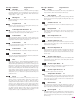

Unplug the kiln or disconnect the power. Remove
the 4 screws holding the controller faceplate to the
switch box. Gently remove the old controller.
Disconnect the wires from the old controller.
If your kiln is
top-loading and origi
-
nally came with a
DTC 100 or 600, the
heat shield inside the
switch box may need
to be moved to give
more clearance for
the new Sentry con
-
troller. Measure the
space between the
heat shield and the
front of the box. If the
spaceis less than 1¾”,
remove the screws
that hold the bottom of the heat shield. These
screws are on the sides near the louvers. Drill new
holes in the switch box next to the bottom 2 holes
used for the heat shield. Move the bottom of the
heat shield back and fasten screws in the new
holes.
Thread the Sentry
wiring harness into
the switch box by in-
serting it in the open-
ing where the control
-
ler goes. Let the end
with the plugs hang
out of the box.
Remove the switch
box from the kiln by
removing the screws
holding the box to the
kiln.
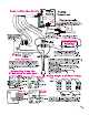
The red wire from the
old controller con
-
nects to the relay(s).
The red wire in the
Sentry wiring harness goes to the same relay termi
-
nal. (See diagram, facing page.) You will notice
that the red Sentry wire has 3 push-on connectors
with jumper wires. If your kiln has 3 relays, you will
use all 3 push-on connectors, 1 for each relay. If
you have 2 relays, cut off the last terminal and
jumper wire. If your kiln has 1 relay, cut off 2
push-on connectors. Cut the wire close to the ter
-
minal that remains (see next photo).
CAUTION: Cut off the extra terminal(s) and jumper
wire(s) unless they attach to
relays. Unconnected wires
that touch a grounded object
candamageyour controller!
Attach the red wire termi
-
nal(s) to the relay(s). Fol
-
low steps 6 and 7 for the
black wire, which also
goes to the relays.
Note how the white, orange, and blue wires of the
old controller are connected to the transformer.
Removing and replacing one wire at a time, con
-
nect the Sentry white, orange, and blue wires to the
transformer the same way. (See Transformers,
next page. Cut off the extra blue wire terminal if
your transformer doesn’t need it.)
Remove the old wiring harness from the switch
box. With the thermocouple wires and the Sentry
connection plugs hanging out of the front of the
switch box, move the box into placeon the kiln. Ar-
range the wires so that when the switch box is fas-
tened to the kiln, the wires and wire nuts will not
touchan element connector or the kiln case.Install
the screws that hold the switch box to the kiln.
Straighten the ends of the thermocouple wires.
Attach them to the thermocouple terminals on the
bottom of the Sentry. (Use the center connectors if
your kiln has only one thermocouple.) Match the
color coding. Make sure the thermocouple wires
are tight and that there is no short.
Attach the two plugs
to the back of the Sen
-
try controller. Care
-
fully insert the Sentry
into the controller
opening on the switch
box. Install the 4 cor
-
ner screws.
24 Ramp-Hold
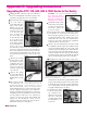
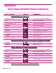
Appendix B: Upgrading Instructions
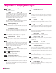
Upgrading the DTC 100, 600, 800 & 1000 Series to the Sentry
The extra wires tied to the harness
are for multiple-zone kilns and the
optional AOP electrical outlet. The
green grounding wire is connected
only if you use a computer interface.
Lever type connectors: if the wire is
too thick, it will break the lever. Do
not force the lever downward.
The button-type thermocouple
connector: Press down, then insert
wires.
Inserting the plugs on the back of
the Sentry.