Sentry 1250 & Sentry 1400 Formerly ST-1200 & ST-1400 Pressure Redistribution Systems Operating Instructions Tridien Medical Revision: AO-SM-ST-02
! WARNING Before operating this medical equipment, it is important to read this manual and to understand the operating instructions and safety precautions. Failure to do this could result in patient injury and/or damage to the product. This equipment generates uses and radiates radio frequency energy and, if not installed and used in accordance with the instructions, may cause harmful interference to other devices in the vicinity (See Section 7.5).
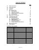
TABLE OF CONTENTS Page 1.0 Safety Precautions 3 2.0 Product Overview 5 3.0 Installation 6 4.0 Operation 4.1 Control Panel 4.2 Key Functions 4.3 Additional Functions 4.4 Settings and System Information 4.5 CPR Operation 8 8 11 12 15 5.0 Maintenance and Cleaning 18 6.0 Troubleshooting Guide 22 7.0 Product Specifications 7.1 Electronic Controller 7.2 Support Surface 7.3 Safety Agency Approvals 7.4 Parts & Accessories 7.5 Product Compliance Declarations 24 25 25 25 26 8.
1.0 SAFETY PRECAUTIONS CAUTION! The Sentry 1250/ST 1200 & Sentry/ST-1400 Systems (“Sentry/ST Systems”) are contraindicated for use with certain medical conditions and treatments. Always consult with the patient’s physician before placing a patient on an alternating pressure system. CAUTION! Bed frames used with the Sentry/ST Systems can vary greatly depending on the specific health care setting, e.g., hospitals, nursing homes, home care.
CAUTION! PE GND terminal in the appliance is only for functional earth. The unit is a Class II device with functional earth and used only for functional purposes. IMPORTANT! Do not return a product for any reason without first contacting Customer Service to obtain authorization (See Section 9.0). Do not place any objects/items, such as blankets, on, or over, the electronic controller. Excessive weight placed on the Sentry/ST System Mattress, i.e.
2.0 PRODUCT OVERVIEW The Sentry/ST Systems are microcontroller-based therapeutic Pressure Redistribution Mattress Systems for patient weights up to 500 pounds/226 kilograms. The Alternating Pressure feature provides pressure relief by sequentially deflating and inflating alternate air cells on a timed interval. It is widely recognized that constant pressure to a bony prominence is the leading cause of skin breakdown.
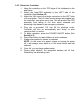
3.0 INSTALLATION NOTE - It is recommended that all shipping and packing material be saved in the event that the product has to be sent back to Tridien. 3.1 Unpacking and Inspection Carefully remove the controller, mattress and all accessories from the shipping cartons. Inspect all items for any damage that may have occurred during shipping. Any damages, or missing components, should be reported to Tridien Customer Service as soon as possible.
3.2.2 Electronic Controller: 1. Hang the controller on the TOP edge of the footboard on the bed frame. 2. Attach the hose/CPR assembly to the LEFT side of the controller (See Section 4.5). 3. Attach the LAL hose to the single connector on the LEFT side of the controller. The LAL hose should always be plugged into the controller, even when not in use. This will prevent the CPR assembly from falling to the floor when released and becoming a trip hazard in an emergency situation. 4.
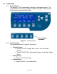
4.0 OPERATION 4.1 Control Panel The Sentry/ST-1400 control panel is shown in the diagram below. The control panels for the Sentry 1250/ST-1200 & Sentry/ST-1400 controller are the same except as noted below: Sentry 1250/ST1200 ONLY Figure 1: Control Panels 4.2 Key Functions The keypad has three (3) types of touch keys: 1. Function Keys: Sentry/ST-1400: Therapy, Max, Fowler, LAL and Inflate Bolsters Sentry 1250/ST-1200: Alternating Pressure, Float, Max, Fowler & LAL 2.
POWER ON/OFF (All Sentry/ST Systems) When the power cord is first inserted in the AC socket on the back cover, the unit goes into Standby Mode and a green LED will blink every 3 seconds until the POWER ON/OFF button is pressed. Press the POWER ON/OFF button to start system operation. The Main Screen shown in Figure 2 will appear. However, the pressure reading will vary from the figure below.
LOW AIR LOSS (All Sentry/ST Systems) This key activates or deactivates the LAL feature. When activated, LAL is shown on the display and a gentle diffused flow of air is delivered through the LAL coverlet (Sentry/ST-1400), or the mattress (Sentry 1250/ST1200). The air will begin to flow only after the mattress has reached the set pressure, either after initial installation or in any mode such as AP, Float, or MAX. The air flow will also be temporarily interrupted while the raised bolster is inflating.
Inflating these bolsters increases bolster height on the sides of the mattress. Integrated bolsters and raised bolsters are inflated to 60 mmHg. This value is not adjustable. 4.3 Additional Functions LOCK KEYPAD (All Sentry/ST Systems) This key locks all keys, including the Power ON/OFF key. Press and hold for 2 seconds to activate. The corresponding blue LED is lit. Press and hold for 2 seconds to unlock.
4.4 Settings and System Information (All Sentry/ST Systems) MENU Press this key to enter the MAIN MENU options screen. Once in the Main Menu, use the ARROW keys to select the desired option and then press the MENU key a second time to save the selected option. ARROWS ARROW keys moves the selection arrow up or down one row at a time and are also used to increase/decrease numerical values. 4.4.
1. Patient Setup This option is used to set the patient’s weight. The Controller automatically adjusts the pressure values for Float and Alternating Pressure modes based on the patient’s weight. Resetting the patient’s weight at any time will override any user changes to AP and/or Float Pressures entered directly on the main screen or through the Advanced Settings. However, Fowler Boost and Cycle Time do not reset. They must be adjusted manually. By default, Fowler Boost is 20% and Cycle time is 6 minutes.
SET FLOAT Figure 7: Set Pressure Menu Figure 8: Float Pressure Adjustment Use the Up and Down arrow keys to select Float. Press the Enter/Menu key. Once Float is selected, (Figure 8), use the Up and Down arrow keys to set the desired float pressure. When done, press the Enter/Menu key to save and return to the Main Screen. SET AP Figure 9: Set Pressure Menu Figure 10: AP Pressure Adjustment Use the Up and Down arrow keys to select AP. Press the Enter/Menu key.
Use the Up and Down Arrow keys to set the desired Fowler Boost percentage increase. When done, press the Enter/Menu key to save and return to the Main Screen. SET CYCLE Use the Up and Down arrow keys to select Set Cycle. Press the Enter/Menu key. The default cycle time is 6 minutes. Figure 12: AP Cycle Time Adjustment Use the Up and Down arrow keys to set the desired Cycle time. When done, press the Enter/Menu key to save and return to the Main Screen.
IMPORTANT! The CPR pull is designed to attach to the controller with a specific orientation. Make sure you align the CPR pull key with the CPR receptacle on the controller and that the CPR label is visible from the front: 1. 2. ALWAYS align the CPR “key” with the key on CPR receptacle. Completely insert the CPR pull until a “click” is heard. (See Figures 14A, 14B, 14C). 4.5.
5. Obtain a new hose of the same length and apply appropriate color code label to one end of the hose (See Figure 15A). Labels and hoses can be purchased through Tridien. Integrated Bolster BLUE Raised Bolster GREEN KEY B Zone BLACK Figure 15A: Color-Coding of CPR Hoses A Zone RED Figure 15B: Color-Coded Attachment Guide for CPR Assembly IMPORTANT! Always maintain color coding convention when changing CPR hoses. 6. Connect hose to the appropriate color coded connector inside mattress.
Figure 17: Replacement of CPR Hose 9. Repeat steps 2-8 if multiple hoses need replacement. 10. Re-apply tubing wrap. 5.0 MAINTENANCE AND CLEANING IMPORTANT! All disinfection should be done using a “hospital-grade” disinfectant registered with the Environmental Protection Agency (EPA) and in accordance with the manufacturer’s specified instructions. Check manufacturer’s instructions before use. 5.1 Electrical Controller The electronic controller is easy to maintain: 5.1.
5.1.2 The exterior of the controller and CPR assembly should be periodically wiped down with a cloth dampened with disinfectant. CAUTION! DO NOT spray disinfectant directly on the electrical controller, or immerse the controller in any type of liquid. This could result in a severe electrical hazard. 5.1.3 Before plugging in the controller, check the power cord for electrical hazards, e.g., cuts, exposed wires, worn insulation, etc.
an intermediate level disinfectant, such as ProTech1. Bleach and disinfectant should be used according to the manufacturer’s instructions. To determine the amount of bleach or disinfectant to use, determine the amount of water in the washer and then follow the manufacturer’s dilution instructions. Soak the coverlet in the disinfectant or bleach during the wash cycle. Rinse thoroughly in clean water and dry before use. NOTE! 2.
The air cell assembly does not routinely need to be cleaned or disinfected between patients. If cleaning/disinfection is required, follow instructions in Section 5.2.2 above. All air cells, including the bolsters are fully accessible and easily replaced. 5.5 Foam Overlay The foam mattress is fully enclosed in a urethane cover and should not require cleaning. However, if it does become “visibly” soiled, it may be wiped down with disinfectant, ensuring that all surfaces come in contact with the disinfectant.
6.0 TROUBLESHOOTING GUIDE 6.1 Pressure Relief System Problem Cause Solution 1. Alarm is on The air cell alarm is activated any time the actual pressure in the air cells does not reach the programmed set pressure in approximately 10 minutes. The alarm will activate if the actual pressure is beyond the tolerance of 2mmHg greater or lower than the set pressure. Low pressure is usually an indication of an air leak in the system. High pressure is usually an indication of a kinked hose.
6.0 TROUBLESHOOTING GUIDE (CONTINUED) 6.1 Pressure Relief System Problem 4. Air is not constantly flowing into the Low Air Loss Coverlet or inside the mattress Cause Solution The internal pump gives priority to the Allow air cells to reach set pressure. air cells in the mattress. Once the air cells are inflated to the set pressure, air will then be directed to the coverlet or mattress. 5. Display readings appear scrambled Power surges can cause the controller to temporarily malfunction.
7.0 PRODUCT SPECIFICATIONS 7.1 Electronic Controller Electrical Specifications: Input Voltage AC Input Frequency Current Consumption Circuit Protection Mode of Operation Protection Against Electric Shock 115V 60 Hz 1.75A <60W Double Fused, 250V, 3.
7.2 Support Surface Specifications (Continued): Height (Inches) Length (Inches) Width (Inches): Weight (Pounds) 7.3 6.5 80 36 (39 and 42 also available) 30 Safety Agency Approvals: ETL Listed to standard for safety of Medical Electrical Equipment Conforms to UL 60601-1, First Edition with respect to Electrical Shock, Fire and Mechanical Hazards Certified to CAN/CSA STD C22.2 No. 601.1 7.
7.5 Product Compliance Declarations 7.5.1 Guidance and Manufacturer’s Declaration – Electromagnetic Emissions Guidance and Manufacturer’s Declaration – Electromagnetic Emissions The Sentry/ST System is intended for use in the electromagnetic environment specified below. The customer or the user of the Sentry/ST System should assure that it is used in such an environment. Emissions test Compliance Electromagnetic environment – guidance The Sentry/ST System uses RF energy only for its internal function.
7.5.2 Guidance and Manufacturer’s Declaration – Electromagnetic Immunity Guidance and Manufacturer’s Declaration – Electromagnetic Immunity The Sentry/ST System is intended for use in the electromagnetic environment specified below. The customer or the user of the Sentry/ST System should assure that it is used in such an environment.
7.5.3 Guidance and Manufacturer’s Declaration – Electromagnetic Immunity - Non Life Supporting Guidance and Manufacturer’s Declaration – Electromagnetic Immunity The Sentry/ST System is intended for use in the electromagnetic environment specified below. The customer or the user of the Sentry/ST System should assure that it is used in such an environment.
7.5.4 Recommended Separation Distances Recommended Separation Distances Between Portable And Mobile RF Communications Equipment And The Sentry1250/ST-1200/1400 The Sentry/ST System is intended for use in an electromagnetic environment in which radiated RF disturbances are controlled.
8.0 WARRANTY INFORMATION LIMITED WARRANTY Tridien Medical (“Tridien”) warrants each of its products to perform in accordance with established specifications for the following time periods, starting from the date the product was shipped from the Tridien facility.
9.0 PRODUCT RETURN The Sentry/ST Systems have been designed to provide you with years of trouble-free service. However, in the event that the product needs to be returned for any reason, such as calibration or repair, the following return procedure must be followed. Failure to follow this procedure may result in unnecessary delays. Return Procedure Before returning a product to Tridien: 1. Contact Customer Service at 800-474-4225 or 954-340-0500 and obtain a Return Material Authorization (RMA) number. 2.
Notes Page 32 of 34
Notes Page 33 of 34
Notes Page 34 of 34
Tridien Medical th 4200 NW 120 Avenue Coral Springs, FL 33065 Phone: 954-340-0500 FAX: 954-340-0511 Web Site: tridien.