
Installation Guide


5
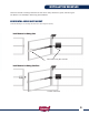
Open and close gate by hand. If binding occurs, adjust the
strike bracket and/or lock mounting bracket until the lock
sits in the strike bracket without any binding. Check for
alignment of strike pin with slot in the lock housing. (Fig. E)
Fully tighten lock nuts on both brackets.
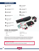
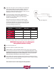
You are now ready to power the lock. Attach the two
wires from the electric lock to those leading to the correct
terminals on your operator board. (For USAutomatic
openers, see Wiring Chart)
When using the electric lock with other brands of gate
openers, it is important to note that the lock is designed
for intermittent activation only. The electric lock only needs
power upon opening. Power applied for extended periods
of time will damage the electric lock.
You are now ready to test the lock for proper operation with the operator.
IMPORTANT! Keep hands clear of any Moving parts
during powered operation or testing!
Re-connect operator arm.
Reconnect power to operator (motor plugs)
Initiate operator to open and visually observe lock to see if Lock Pin retracts
during opening and extends during closing. It is important that power is only
applied during the opening cycle. All power to the electric lock should be
off during the closing cycle or in the rest position. If the lock retracts and
extends properly, install strike pin with clevis clip or padlock.
Gate operator limit switches should be reset at this time if necessary to ensure
proper lock closure. After all adjustments and tests have been completed, tighten
nuts and cut off any excess bolt length.
The electric lock is now ready for full operation.
11
10
Figure E
Check Alignment
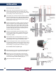
Wiring Chart for USAutomatic Openers
Operator Green Wire + Blue Wire - Switch
Patriot J1 Solenoid Lock Battery - Neg DS2 #1 - On
Patriot RSL J1 Solenoid Lock Battery - Neg DS2 #1 - On
Ranger J2 Pin 4 Battery - Neg DS1 #5 - On
Sentry J2 Pin 7 Battery - Neg DS1 #5 - On
12
13
14
15