Server Technology Solutions for the Data Center Equipment Cabinet Sentry Commander - PT40 Installation and Operations Manual © 2004 Server Technology, Inc. All rights reserved.
Instructions This symbol is intended to alert the user to the presence of important operating and maintenance (servicing) instructions in the literature accompanying the appliance. Dangerous Voltage This symbol is intended to alert the user to the presence of un-insulated dangerous voltage within the product’s enclosure that may be of sufficient magnitude to constitute a risk of electric shock to persons.
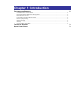
Table of Contents CHAPTER 1: INTRODUCTION 1 Features and Benefits .......................................................................................................................2 Technical Support ............................................................................................................................3 Quick Start Guide.............................................................................................................................
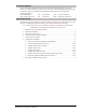
Chapter 1: Introduction FEATURES AND BENEFITS 2 Communication Access Modes ........................................................................................................2 Power Distribution & Remote Management ....................................................................................2 Pass-Thru Port Access......................................................................................................................2 Load and Environment Measurement ..............................
Introduction The Server Technology Inc. Sentry family of products provides easy, practical, and secure solutions for power distribution, power management and load-measurement for remote internetworking equipment and branch AC circuits. The Sentry PT40 Commander continues to support the elimination of unnecessary trips to remote locations by allowing remote control of the power on/off status for distant critical equipment, minimizing the impact of locked-up devices on mission-critical networks.
Technical Support Server Technology understands that there are often questions when installing and/or using a new product. Free Technical Support is provided from 8:30 AM to 5:00 PM, Monday-Friday, Pacific Time. See Technical Support in Warranty, Product Registration and Support for more information. Server Technology, Inc. 1040 Sandhill Drive Reno, Nevada 89521 USA Tel: 775.284.2000 Fax: 775.284.2065 Web: www.servertech.com Email: support@servertech.
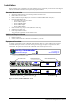
Chapter 2: Installation STANDARD ACCESSORIES ADDITIONAL REQUIRED ITEMS EQUIPMENT OVERVIEW SAFETY PRECAUTIONS INSTALLING THE POWER INPUT RETENTION BRACKET MOUNTING CONNECTING TO THE POWER SOURCE CONNECTING DEVICES CONNECTING TO THE COMMANDER Serial (RS232) port.................................................................................................................8 Ethernet port...........................................................................................................................
Installation Before installing your Commander, refer to the following lists to ensure that you have all the items shipped with the unit as well as all other items required for proper installation.
Safety Precautions This section contains important safety and regulatory information that should be reviewed before installing and using the Commander. For input and output current ratings, see Power Ratings in Appendix C: Technical Specifications. Only for installation and use in a Service Access Location in accordance with the following installation and use instructions. This equipment is designed to be installed on a dedicated circuit. Dedicated circuit must have circuit breaker or fuse protection.
Connecting to the Power Source The input power cord must first be attached to the unit before connecting the unit to the power source. Each outlet powers up sequentially, with a two-second delay between each outlet, eliminating a potential blown primary fuse or circuit breaker from excessive in-rush current. To attach the power cord to the unit: 1. 2. Plug the female end of the power cord firmly into its connector at the base. Use a screwdriver to tighten the two screws on the retention bracket.
Chapter 3: Operations INTERFACES Outlet Naming and Grouping Usernames and Passwords 10 10 10 HTML INTERFACE Logging In Outlet Control Individual..............................................................................................................................12 Group....................................................................................................................................12 Environmental Monitoring Input Load .............................................................
Operations Interfaces The Sentry has two interfaces: the HTML interface accessed via the HTTP enabled Ethernet connections and the command line for serial and Telnet connections. Outlet Naming and Grouping For commands requiring an outlet name, you may specify it in one of two ways: a predefined absolute name or a descriptive name assigned by an administrator. Absolute names are specified by a period (.) followed by the tower letter, the infeed letter and outlet number.
HTML Interface The HTML interface is constructed of three major components: the System Location bar, the User/Navigation bar and the Control Screen. The System Location bar displays the Sentry’s location and IP address as well as the current Control Screen title. The User/Navigation bar displays the current user and privilege level and provides access to all HTML pages. And the Control Screen is used to display current data and allow changes to outlet states or system configuration.
Outlet Control The Outlet Control section offers access to the Individual and Group outlet control pages. From the Individual and Group pages, the user can review and manipulate power control functions for all outlets and groups assigned to the current user. Both pages include the outlets absolute and descriptive names, the Outlet Status reported to the Sentry by the outlet, the current Control State being applied by the Sentry and the outlet load in amperes.
Configuration The Configuration section offers access to all unit configuration options including Network, Telnet/HTTP, Serial Ports, Outlets, Groups, Users, FTP, Proxy/SNTP and SNMP. This section is available to administrative level users only.
Telnet/SSH The Telnet/SSH configuration page used to enable or disable Telnet and SSH support and configure the port number that the Telnet or SSH server watches. For more information on SSH see page 43 in Chapter 4: Advanced Operations. Enabling or disabling Telnet or SSH support: Select Enabled or Disabled from the appropriate Server drop-down menu and press Apply. Changing the Telnet or SSH server port number: In the appropriate Port field, enter the port number and press Apply.
Serial Ports The Serial Ports configuration page is used for maintenance of all serial/Pass-Thru ports. NOTE: Pass-Thru connections may only be initiated from the command line interface via a direct serial or Telnet session. Setting the data-rate for all serial/Pass-Thru ports: Select the serial/Pass-Thru port data-rate from the drop-down menu and press Apply. Creating a descriptive Pass-Thru port name: Click on the Edit link in the Action column next to the port to be configured.
Outlets The Outlets configuration page is used for assignment and/or editing of outlet descriptive names and wakeup states. Editing the outlet descriptive name: Click on the Edit link in the Action column next to the outlet to be configured. On the subsequent Outlet Edit page, enter the descriptive name. Up to 24 alphanumeric and other typeable characters (ASCII 33 to 126 decimal, spaces and colon characters are not allowed) are allowed. Press Apply.
Changing a user’s access privilege level: The Sentry has four defined access privilege levels; Admin, User, On-Only and View-Only: • Admin: Full-access for all configuration, control (On, Off, Reboot), status and Pass-Thru. • User: Partial-access for control (On, Off, Reboot), status and Pass-Thru of assigned outlets, groups and serial/Pass-Thru ports. • On-Only: Partial-access for control (On), status and Pass-Thru of assigned outlets, groups and serial/Pass-Thru ports.
FTP The FTP configuration page is used for setup and maintenance of all settings required to perform an FTP firmware upload. See Appendix B: Uploading Firmware for more information on uploading firmware. Setting the FTP Host IP Address: Enter the IP address in the Host IP Address field and press Apply. Setting the FTP username: Enter the FTP server username in the Username field, and press Apply. Setting the FTP password: Enter the FTP server password in the Password field, and press Apply.
Configuring input feed traps: Click on the Input Feed Traps link. On the subsequent Input Feed Traps page, select or deselect the desired traps and press Apply. For Load traps, enter a maximum load value for the infeed in the High Load Threshold field and press Apply. The High Load Threshold value may be 0 to 255 (in amperes). Configuring outlet traps: Click on the Outlet Traps link. On the subsequent Outlet Traps page, select or deselect the desired traps and press Apply.
Command Line Interface Logging In Logging in through Telnet requires directing the Telnet client to the configured IP address of the unit. Logging in through the Console (RS232) port requires the use of a terminal or terminal emulation software configured to support ANSI or VT100 and a supported data rate (300, 1200, 2400, 4800, 9600, 19200, 38400, 57600, or 115200 BPS) - 8 data bits-no parity-one stop bit and Device Ready output signal (DTR or DSR). To log in by RS-232 or Telnet: 1. Press Enter.
Administrative Command Summary (continued) Delete Groupfromuser Removes access to one or more groups for a user Delete Outletfromgroup Deletes an outlet from a group name Delete Outletfromuser Removes access to one or all outlets for a user Delete Portfromuser Removes access to one or all serial/Pass-Thru ports List User Displays all accessible outlets/groups/ports for a user List Users Displays privilege levels for all users Remove Group Deletes a group name Remove User Deletes a user account
Operations Commands Operations commands manage outlet states, provide information about the Sentry environment and control session operations. NOTE: Users must be granted access to affect any change in outlet state. Turning outlets on The On command turns on one or more outlets. When the command completes, a display indicating all outlets affected and their current states will be displayed.
Displaying outlet status The Status command displays the on/off status of one or more outlets. The command displays the status of only those outlets for which the current username has power control access. This display includes the outlet absolute and descriptive names, the Outlet State reported to the Sentry by the outlet and the current Control State being applied by the Sentry. If you do not specify any parameter with this command, the status of all accessible outlets is displayed.
Displaying accessible groups The List Groups command displays accessible groups for the current user. To display accessible groups: At the Sentry: prompt, type list groups and press Enter. Example The follow command displays all accessible groups for the current user: Sentry: list groups Groups: ServerGroup_1 RouterGroup_1 Displaying outlets assigned to a group The List Group command displays outlets assigned to the specified group name.
Connecting to a serial device The Connect command allows Pass-Thru serial connection to devices attached to one of the two standard serial ports (Console, Modem,) or a Pass-Thru port. To connect to a serial device: At the Sentry: prompt, type connect, followed by the serial/Pass-Thru port name and press Enter.
Administration Commands Administration commands may only be issued by a user with administrative privileges, such as the predefined Admn user or another user who has been granted administrative privileges with the Set User Admnpriv command. User Administration Creating a user account The Create User command creates a user account with the specified username and password. See Usernames and Passwords in this chapter for more information.
Setting user access level privileges The Set User Access command sets the access level privileges for a user. The Sentry has four defined access privilege levels; Admin, User, On-Only and View-Only. For more information on user access levels, see Changing a user’s access privilege level: on page 17. The administrator may also grant administrative privileges to other user accounts allowing the Sentry to have more than one administrative-level user.
Adding outlet access to a user The Add OutletToUser command grants a user access to one or all outlets. To grant access for more than one outlet, but not all outlets, you must use multiple Add OutletToUser commands. To grant outlet access to a user: At the Sentry: prompt, type add outlettouser, optionally followed by an outlet name and a username. Press Enter, or Type add outlettouser all, followed by a username and press Enter.
Deleting serial/Pass-Thru port access for a user The Delete PortFromUser command removes a user’s access to a serial/Pass-Thru port. You cannot remove access to any serial/Pass-Thru port for an administrative level user. To delete serial/Pass-Thru port access for a user: At the Sentry: prompt, type delete portfromuser, optionally followed by a Port name and a username. Press Enter.
Adding an outlet to a group The Add OutletToGroup command adds an outlet to a group. To add more than one outlet, but not all outlets, you must use multiple Add OutletToGroup commands. To add an outlet to a group: At the Sentry: prompt, type add outlettogroup, optionally followed by an outlet name and group name. Press Enter, or Type add OutletToGroup, followed by all and the group name. Press Enter.
Displaying outlet information The Show Outlets command displays information about all outlets. This information includes: • • Descriptive outlet name, if applicable Outlet wakeup state setting To display outlet information: At the Sentry: prompt, type show outlets and press Enter. Example The following command displays all outlet information: Sentry: show outlets Outlet ID Outlet Name Wakeup State .A1 .A2 .A3 .
Enabling or disabling active signal checking for serial/Pass-Thru connections The Set Port Dsrchk command enables or disables active signal checking for serial/Pass-Thru connections to devices attached to any of the available serial ports. To enable or disable active signal checking for serial connections: At the Sentry: prompt, type set port dsrchk, followed by serial port name, on or off, and press Enter, or Type set port dsrchk all, on or off, and press Enter.
Displaying serial/Pass-Thru port information The Show Ports command displays information about all serial/Pass-Thru ports. This information includes: • • • • Serial/Pass-Thru port data rate Modem port initialization strings Descriptive port name, if applicable DSR signal checking settings To display serial port information: At the Sentry: prompt, type show ports and press Enter.
Displaying system configuration information The Show System command displays all system configuration information. • • • • • Firmware version NIC module serial number and MAC address Hardware revision code and Flash size Uptime since last system restart System location description See Chapter 4: Advanced Operations on page 41 for more information on SNMP. To display system configuration information: At the Sentry: prompt, type show system and press Enter.
Displaying Infeed information The Show Infeeds command displays information about all infeeds. This information includes the absolute and descriptive infeed names. To display tower information: At the Sentry: prompt, type show infeeds and press Enter. Example Sentry: show infeeds Input Feed ID Input Feed Name .AA HQ_1_Infeed_A Displaying the Sentry firmware version The Version command displays the Sentry firmware version.
Displaying network configuration information The Show Network command displays TCP/IP, Telnet, SSH, Web, SSL and SNMP configuration information.
HTTP Administration NOTE: A restart is required after setting or changing ANY Telnet/Web configurations. See Performing a warm boot on page 35 for more information. Enabling and disabling HTTP support The Set HTTP command is used to enable or disable HTTP support. To enable or disable HTTP support: At the Sentry: prompt, type set http, followed by enabled or disabled and press Enter.
FTP Administration You may upload new versions of firmware into the Sentry using File Transfer Protocol (FTP). This allows access to new firmware releases for firmware improvements and new features additions. The following commands are used to configure the Sentry for an FTP firmware upload. See Appendix B: Uploading Firmware for more information on initiating a FTP firmware upload. Setting the FTP Host IP address The Set FTP Host command sets the FTP host IP address allowing for firmware file uploads.
Displaying FTP configuration information The Show FTP command displays all FTP configuration information. • • • FTP Host IP address FTP Host username and password Firmware filepath and filename To display FTP configuration information: At the Sentry: prompt, type show ftp and press Enter. Example The following command displays the FTP configuration information: Sentry: show ftp FTP Configuration Host IP Address: Username: Password: Directory: Filename: 12.34.56.
Chapter 4: Advanced Operations SSL Enabling and Setting up SSL Support SSL Technical Specifications 42 42 42 SSH Enabling and Setting up SSH Support SSH Technical Specifications 43 43 43 SNMP MIB, OID and Support Enabling and Setting up SNMP Support SNMP Traps Configuring Traps 44 44 44 46 47
Advanced Operations SSL Secure Socket Layers (SSL) version 3 enables secure HTML sessions between a Sentry Remote Power Manager and a remote user. SSL provides two chief features designed to make TCP/IP (Internet) transmitted data more secure: • • Authentication – The connecting client is assured of the identity of the server. Encryption – All data transmitted between the client and the server is encrypted rendering any intercepted data unintelligible to any third party.
SSH Secure Shell (SSH) version 2 enables secure network terminal sessions between a Sentry Remote Power Manager and a remote user over insecure network. SSH provides an encrypted terminal sessions with strong authentication of both the server and client, using public-key cryptography and is typically used as a replacement for unencrypted Telnet.
SNMP The Sentry family of products supports the Simple Network Management Protocol (SNMP). This allows network management systems to use SNMP requests to retrieve information and control power for the individual outlets. The Sentry includes an SNMP v1 agent supporting standard MIB I and MIB II objects. A private enterprise MIB extension (Sentry3 MIB) is also supported to provide remote power control. NOTE: For security, SNMP support is disabled by default.
Setting the trap timer The Set Traptime command sets the timer period between repeated error-condition traps. The valid range for the timer period is 1 to 65535 (in seconds). The default value for the timer period is 60 seconds. To set the trap timer: At the Sentry: prompt, type set traptime, followed by the timer period and press Enter.
SNMP Traps The Sentry supports three types of SNMP traps. Traps are enabled at the tower (T), infeed (I) or outlet (O) level. Trap Summary Name Level(s) Status T, I, O Description Operational status change Change O Control status change Load I Input load out of limit All traps include the Location of the Sentry as defined with the Set Location command. See Creating a location description in Chapter 3: Operations for more information.
Load Trap The Load trap is generated whenever the total input load on an infeed exceeds a preset threshold. Load traps include the reported input load, load status, Location of the Sentry, and identifier and name of the affected infeed. Any error state generates a Load trap and triggers the trap timer. A new trap is generated at the end of every timer period until the Load returns to a non-error status.
Enabling or Disabling a Load trap The Set Trap Infeed Load command is used to enable or disable an Infeed Load trap. To Enable or Disable a Load trap: At the Sentry: prompt, type set trap infeed load, followed by the infeed name, and on or off. Press Enter, or Type set trap infeed load all, followed by on or off and press Enter. Examples The following command enables the Load trap for second infeed on the first tower, using the infeed’s absolute name: Sentry: set trap infeed load .
Displaying trap configuration information The Show Traps command displays information about all traps. To display trap information: At the Sentry: prompt, type show traps and press Enter. Example The following command requests trap configuration information: Sentry: show traps Tower trap configuration: Tower ID Tower Name Status Trap .A Florida_HQ_1 ON Input feed trap configuration: Input Feed ID Input Feed Name Status Trap Load Trap .
Chapter 5: Appendices APPENDIX A: RESETTING TO FACTORY DEFAULTS 52 To reset to factory defaults from the HTML interface ...................................................................52 To reset to factory defaults from the command line.......................................................................52 To reset to factory defaults using the reset button..........................................................................
Appendices Appendix A: Resetting to Factory Defaults You may reset the non-volatile RAM that stores all configurable options. This clears all administratoreditable fields and resets all command line configurable options to their default values, including all user accounts. You may reset the unit to factory defaults from the command line or the HTML interface, or by pressing the reset button. You must have administrator-level privileges to issue the command.
Appendix C: Technical Specifications Models Model Voltage PT40-H404-1-02 100-120V, 50/60Hz IEC 60320/C20 Inlet* 4 NEMA 5-20R Outlets Additional Ports 4 Pass-Thru PT40-H404-2-02 208-240V, 50/60Hz IEC 60320/C20 4 IEC 60320/C13 4 Pass-Thru * Input cordset selected at time of purchase.
Data Connections RS-232 port Sentrys are equipped standard with an RJ45 DTE RS-232c serial port. This connector may be used for direct local access or from other serial devices such as a terminal server. An RJ45 crossover cable is provided for connection to an RJ45 DCE serial port.
Pass-Thru Port The Sentry is equipped with four RJ12 DTE Pass-Thru ports for connection to serial devices. RJ12 crossover cables are provided for connection along with adapters for connection to standard RS-232C 9 and 25 pin, DTE and DCE serial ports. For information on additional available adapters for non-standard applications, please review Data & ShutDown Adapters, Cables & Kits on the Server Technology website - Tech Library, Technical Notes.
Appendix D: Warranty, Product Registration and Support Warranty and Limitation of Liability Server Technology, Inc. agrees to repair or replace Products that fail due to a defect within twelve (12) months after the shipment date of each Product unit to Buyer (“Warranty Period”). For purposes of this Agreement the term “defect” shall mean the Product fails to operate or fails to conform to its applicable specifications.
Technical Support Server Technology understands that there are often questions when installing and/or using a new product. Free Technical Support is provided from 8:30 AM to 5:00 PM, Monday-Friday, Pacific Time. Server Technology, Inc. 1040 Sandhill Drive Reno, Nevada 89521 USA Tel: 775.284.2000 Fax: 775.284.2065 Web: www.servertech.com Email: support@servertech.
Server Technology, Inc. Server Technology, Inc. 1040 Sandhill Drive Reno, NV 89521 USA toll free +1.800.835.1515 tel +1.775.284.2000 fax +1.775.284.2065 www.servertech.com sales@servertech.com Sentry, Commander, Environmental Monitoring Control Unit, Pass-Thru and Sentry Secure Agent are trademarks of Server Technology, Inc. 301-0402-1 Rev. C (042304) © 2004 Server Technology, Inc. All rights reserved.