
Installation Guide
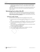
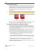
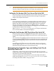
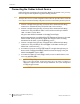
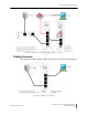

Table Of Contents
- Sensys Networks VDS240 Wireless Vehicle Detection System
- Access Point Controller Card (APCC) Installation Guide
- Contents
- Introduction
- Overview
- Access Point Controller Card (APCC)
- Types of APCC Configurations
- APCC Package Contents
- SPP Package Contents
- Additional Parts and Equipment Required
- 1. Cabling – a minimum of one straight-through Ethernet cables are required.
- 2. Laptop PC and TrafficDOT software – if contact closure cards will be configured via TrafficDOT's GUI, a suitable host is required.
- 3. Contact closure card functions can be configured from the switches on the front panel eliminating the need for a laptop PC and TrafficDOT.
- APCC Installation Considerations
- SPP Installation Considerations
- APCC Installation Procedures
- SPP Installation Procedures
- Tools Required for SPP Installation
- Step-by-Step Procedures
- Installing the Mounting Plate on Poles
- Installing the Mounting Plate on Walls
- Installing the Mounting Plate on Beams
- Determining the Type of SPP Radio Bulkhead Connector
- Connecting the Cable to an SPP Radio with the Hex-head Connector
- Step-by-Step Procedures
- Figure 6.6. Remove the factory-installed cap
- Figure 6.7. Inspect the factory-installed gasket
- Figure 6.8. Replace damaged or used gaskets
- Figure 6.9. Thread cable through connector A
- Figure 6.10. Thread cable through connector B
- Figure 6.11. Ethernet cable bushing chart (not to scale)
- Figure 6.12. Fit bushing onto cable between connector A and connector B
- Proper Fit (little to no gap between edges of cut)
- Improper Fit (gap between edges of cut)
- Proper Fit (bushing fully seated into guides)
- Improper Fit (bushing poorly seated into guides)
- Proper Fit (recessed bushing, smooth face)
- Improper Fit (bushing not recessed, pinched edge, mushroomed face)
- Removing the Cable Connection
- Configuration
- Overview
- Configuring Channels With the Front-Panel Interface
- Starting TrafficDOT and Connecting to an APCC
- Configuring Channels with TrafficDOT
- Defining Sensor-to-Channel Mappings
- Exiting TrafficDOT
- X Mode LED Displays for Slot Numbers
- Circuit-board Dip Switch SW1 Settings
- Circuit-board Dip Switch SW2 Settings
- Pre-Installation Worksheets
- Contact Closure Card External Interfaces

Chapter 5
18 Access Point Controller Card (APCC)
Installation Guide Sensys Networks, Inc.
Factory Default Card ID
Card IDs are implemented on Sensys Networks contact closure cards via two dip
switches found on the side of the card. In this guide, the switches – named SW1
and SW2 respectively – are referred as circuit-board dip switches to differentiate
them from other dip switches on the front-panel of contact closure cards.
A default Card ID of “03-15” is assigned at the factory and is shown in the
following figure.
NOTE:
On the card, switches SW1 and SW2 are not as close to one another as shown in the figure.
Figure 5.1. Default card ID (all dips down)
Before proceeding, ensure that switches SW1 and SW2 are set as in Figure 5.1 and,
additionally, that all front-panel switches are in the right-hand position.
Querying the Backplane for an Assigned Address
The APCC support an operating mode (called X mode) that queries the traffic
controller backplane for an address. Because it can be difficult to determine from
visual inspection if the backplane dictates card addresses, the standard practice is
to use X mode to see if this is the case.
X mode uses the four front-panel channel LEDs to visually indicate the backplane
address assigned by the controller (if any). (Refer to
Appendix A: X Mode LED
Displays for Slot Numbers
for a figure that depicts how the channel LEDs are used.)
Follow these steps to use X mode to query the controller for a card address:
1. Verify that the APCC is set to its default Card ID and that all front-panel
switches are in the right-hand position.
2. Reset the APCC by pressing the master reset button (located on front-panel
next to channel LEDs) or removing the unit from the cabinet and re-inserting
it.
3. Observe the front-panel channel LEDs. Match the pattern of lighted LEDs
with the figure in
Appendix A: X Mode LED Displays for Slot Numbers.
The address value that matches the LED display pattern (from Appendix A) is the
slot number component of the Card ID.
DRAFT