
Installation Guide
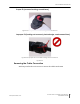

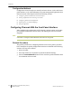
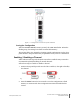
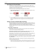
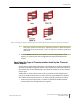
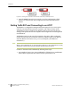
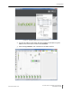
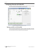
Table Of Contents
- Sensys Networks VDS240 Wireless Vehicle Detection System
- Access Point Controller Card (APCC) Installation Guide
- Contents
- Introduction
- Overview
- Access Point Controller Card (APCC)
- Types of APCC Configurations
- APCC Package Contents
- SPP Package Contents
- Additional Parts and Equipment Required
- 1. Cabling – a minimum of one straight-through Ethernet cables are required.
- 2. Laptop PC and TrafficDOT software – if contact closure cards will be configured via TrafficDOT's GUI, a suitable host is required.
- 3. Contact closure card functions can be configured from the switches on the front panel eliminating the need for a laptop PC and TrafficDOT.
- APCC Installation Considerations
- SPP Installation Considerations
- APCC Installation Procedures
- SPP Installation Procedures
- Tools Required for SPP Installation
- Step-by-Step Procedures
- Installing the Mounting Plate on Poles
- Installing the Mounting Plate on Walls
- Installing the Mounting Plate on Beams
- Determining the Type of SPP Radio Bulkhead Connector
- Connecting the Cable to an SPP Radio with the Hex-head Connector
- Step-by-Step Procedures
- Figure 6.6. Remove the factory-installed cap
- Figure 6.7. Inspect the factory-installed gasket
- Figure 6.8. Replace damaged or used gaskets
- Figure 6.9. Thread cable through connector A
- Figure 6.10. Thread cable through connector B
- Figure 6.11. Ethernet cable bushing chart (not to scale)
- Figure 6.12. Fit bushing onto cable between connector A and connector B
- Proper Fit (little to no gap between edges of cut)
- Improper Fit (gap between edges of cut)
- Proper Fit (bushing fully seated into guides)
- Improper Fit (bushing poorly seated into guides)
- Proper Fit (recessed bushing, smooth face)
- Improper Fit (bushing not recessed, pinched edge, mushroomed face)
- Removing the Cable Connection
- Configuration
- Overview
- Configuring Channels With the Front-Panel Interface
- Starting TrafficDOT and Connecting to an APCC
- Configuring Channels with TrafficDOT
- Defining Sensor-to-Channel Mappings
- Exiting TrafficDOT
- X Mode LED Displays for Slot Numbers
- Circuit-board Dip Switch SW1 Settings
- Circuit-board Dip Switch SW2 Settings
- Pre-Installation Worksheets
- Contact Closure Card External Interfaces

Chapter 7
40 Access Point Controller Card (APCC)
Installation Guide Sensys Networks, Inc.
Figure 7.5. Setting the channel monitor buzzer with front-panel dip switch 1
2. Press the Enter button for five seconds to save the configuration to flash
memory or continue with other configuration activities described in this
section.
Starting TrafficDOT and Connecting to an APCC
TrafficDOT is a configuration manager and monitoring tool for an access point
and all its associated devices (sensors, repeaters, and contact closure cards).
TrafficDOT provides a graphical user interface (GUI) to the network's devices,
settings, and operations. The GUI simplifies both configuration and management
of installations.
TrafficDOT requires an IP network connection to the APCC. When configuring
contact closure cards, the connection is made by cabling a laptop to an APCC or
EX card. (Refer to the section
Cabling Summary in Chapter 5 for additional
information.)
N
OTE
:
Refer to the TrafficDOT Set Up and Operating Guide for a more information on using
TrafficDOT with the Sensys Networks Wireless Vehicle Detection System.
Connect to the APCC with TrafficDOT by following these steps:
1. On a Windows laptop or PC, start TrafficDOT by clicking its icon. TrafficDOT's
Main window opens with the Connect window open in front of it.