
Installation Guide
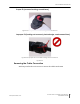

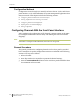
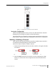
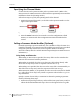
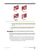
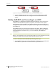
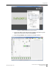
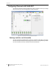
Table Of Contents
- Sensys Networks VDS240 Wireless Vehicle Detection System
- Access Point Controller Card (APCC) Installation Guide
- Contents
- Introduction
- Overview
- Access Point Controller Card (APCC)
- Types of APCC Configurations
- APCC Package Contents
- SPP Package Contents
- Additional Parts and Equipment Required
- 1. Cabling – a minimum of one straight-through Ethernet cables are required.
- 2. Laptop PC and TrafficDOT software – if contact closure cards will be configured via TrafficDOT's GUI, a suitable host is required.
- 3. Contact closure card functions can be configured from the switches on the front panel eliminating the need for a laptop PC and TrafficDOT.
- APCC Installation Considerations
- SPP Installation Considerations
- APCC Installation Procedures
- SPP Installation Procedures
- Tools Required for SPP Installation
- Step-by-Step Procedures
- Installing the Mounting Plate on Poles
- Installing the Mounting Plate on Walls
- Installing the Mounting Plate on Beams
- Determining the Type of SPP Radio Bulkhead Connector
- Connecting the Cable to an SPP Radio with the Hex-head Connector
- Step-by-Step Procedures
- Figure 6.6. Remove the factory-installed cap
- Figure 6.7. Inspect the factory-installed gasket
- Figure 6.8. Replace damaged or used gaskets
- Figure 6.9. Thread cable through connector A
- Figure 6.10. Thread cable through connector B
- Figure 6.11. Ethernet cable bushing chart (not to scale)
- Figure 6.12. Fit bushing onto cable between connector A and connector B
- Proper Fit (little to no gap between edges of cut)
- Improper Fit (gap between edges of cut)
- Proper Fit (bushing fully seated into guides)
- Improper Fit (bushing poorly seated into guides)
- Proper Fit (recessed bushing, smooth face)
- Improper Fit (bushing not recessed, pinched edge, mushroomed face)
- Removing the Cable Connection
- Configuration
- Overview
- Configuring Channels With the Front-Panel Interface
- Starting TrafficDOT and Connecting to an APCC
- Configuring Channels with TrafficDOT
- Defining Sensor-to-Channel Mappings
- Exiting TrafficDOT
- X Mode LED Displays for Slot Numbers
- Circuit-board Dip Switch SW1 Settings
- Circuit-board Dip Switch SW2 Settings
- Pre-Installation Worksheets
- Contact Closure Card External Interfaces

Chapter 7
38 Access Point Controller Card (APCC)
Installation Guide Sensys Networks, Inc.
Specifying the Channel Mode
Contact closure cards operate in either pulse or presence mode. (Refer to the
Sensys Networks VDS240 Wireless Vehicle Detection System Reference Guide for
information about the operating modes.)
Follow these steps to specify the operating mode of the channel.
1. Position front-panel dip switch 7 to the left to select presence mode or to the
right to select pulse mode.
Figure 7.3. Selecting the channel operating mode with front-panel switch 7
2. Press the Enter button for five seconds to save the configuration to flash
memory or continue with other configuration activities described in this
section.
Setting a Presence Mode Modifier (Optional)
Channels operating in presence mode may use a modifier to delay the onset of or
extend the duration of a contact closure. The modifier type and scope is specified
using front-panel dip switches five and six together. (Refer to the Sensys
Networks VDS240 Wireless Vehicle Detection System Reference Guide for more
information.)
Using Delay and Extension
When Delay or Extension are specified, the rotary dial is used to articulate the
numeric value associated with the parameter.
When Delay is specified, the value set on the rotary dial is taken directly. This
allows the 16-step rotary switch to represent values from 0 to 15.
When Delay+16 is specified, the value set on the rotary dial is incremented by 16.
This allows the 16-step rotary switch to represent values from 16 to 31.
When Extension (EXTN / 2) is specified, the value set on the rotary dial is divided
by 2. This allows the 16-step rotary switch to represent values from 0 to 7.5 in ½
step increments.
Specify a contact closure delay or extension for channels operating in presence
mode by following these steps:
1. Position front-panel dip switches 5 and 6 and the front-panel rotary switch to
reflect the desired modifier and scope value. Use the figure below as a guide.