
User's Manual


Test Plan
Invensys Metering Systems Page 6 of 7
the received message match those set in the receiving radio. The original sender
will accept that ACK generated by the receiving radio if and only if the SrcPanID
and SrcAddr in the original message are correct. Below are a few steps that can be
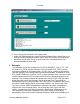
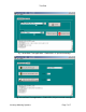
followed to verify proper communication and a couple of screenshots that show the
resulting messages in the test applications message windows. The file
DL_DATA_REQUEST_ACK_1.TXT contains the following text. In the screenshot in
fig. 3, this message has just been sent out and can be seen on the third line in the
message window.
/ This is a test Output File #1
0x0D
0x12 // Length of remaining bytes including CRC
0x0B // DL Data Request
0x01 // Src Addr mode = 8
0x00
0x01 // Pan Id = 0x0001
0x01 // Src Addr
0x01 // Dest Addr Mode = 8
0x00
0x01 // Dest Pan ID = 0x0001
0x02 // Dest ID = 2
0x05 // Lsdu Length
0x01
0x02
0x03
0x04
0x05
0x01 // Ack Monitoring (on)
CRCMSB //CRC PlaceHolders
CRCLSB
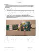
Steps to verify communication between two radios:
1. Connect both radios to RS232 interface boards and power as described
above.
2. Power on both radios.
3. Start the test application for each radio.
4. Set the Filter Type, PanID and Local Address for both radios. For a simple
test use PanID 0x0001 and Local Address 0x01 for the sending radio and
PanID 0x0001 and Local Address 0x02 for the receiving radio and send the
file above which matches these settings.
5. Sending the file DL_DATA_REQUEST_ACK_1.TXT above should result in a
DL_DATA_confirm showing 0xF0 DL_SUCCESS on the sending radio and
an Indication on the receiving radio (see fig. 4 below). Since AckMode is set
to ACK_MONITORING (0x01) in the message, this confirms that the RF ACK
was successful. The message windows on the test apps used should look
like the screenshots below.