
User's Manual

Test Plan
Invensys Metering Systems Page 4 of 7
Introduction
This document contains instructions for setting up communication between multiple
Robert Shaw radios for testing purposes, and describes the use of the InvenStack
test software.
1 Setup Procedures
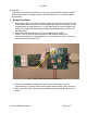
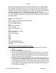
1. Connect the radio to the RS232 interface/control board via the 10 pin connectors
with a ribbon cable as shown in the photograph fig 1. Make sure that pin 1 on the
interface board is connected to pin 1 on the radio (both are near the edge of the
board). The interface board provides voltage level shifting between the PC and
the radio board.
2. Connect the interface board to a PC via a standard RS232 cable.
3. Provide 3.3V DC (limit to 80mA per radio) to the interface board at the
connections shown in the photograph fig 1. Current draw at 3.3V in on power-up
should be about 30mA per radio.
fig. 1 – Serial comm. and power connections
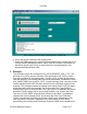
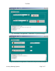
4. Start the InvenStack test application (start one for each radio) on the PC
(screenshot fig. 2). Set up serial communication with the radio in the Com menu.
5. Set up the Filter Type, PanID and Local Address under the DLME tab. See fig. 2
below.
Rese
t