
User's Manual

9
To be used only for the purpose for which it is submitted. All rights reserved to AMDS LLC. Reproduction without written
consent is prohibited.
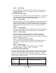
Port DCE
Inputs 1-7 Inputs Contact Closure Alarm Inputs.
Ethernet Bi-directional 10/100Base T Ethernet Port
2. Installation
2.1. Ventilation
The outdoor enclosure is completely sealed from the outside environment
(NEMA 4). A heat exchanger is used to cool internal electronics.
The indoor enclosure is designed to circulate ambient air for cooling. Fans
inside the enclosure are designed to circulate air across the electronics and
power supply.
2.2. Electrical Connections
2.2.1. Grounding
Ensure that all connections to the Ground bus bar are secure. The bus
bar must also be connected to the site’s Halo Ground using the 8AWG
Green/Yellow cable provided with the TGB System.
2.2.2. Power/Battery
!!! Warning
!!!
Do not make any connections with power applied to the system. The
batteries are a source of energy and can be hazardous if shorted.
Exercise caution.
Prior to connecting batteries, disconnect the battery cable from the right
hand side of the rectifier cabinet. Install batteries and connect jumpers to
battery terminals. Before reconnecting battery cable to right hand side of
rectifier cabinet, measure open circuit voltage between pins 1 & 2. The
voltage should be above 24VDC. If the voltage is below 22VDC, do
not
proceed with connection—batteries must first be charged before
installation.
2.2.3. Antenna
The antenna connection is a Type-N female located on the top of the
indoor cabinet (bottom of the outdoor cabinet). The connector is a
bulkhead mounted surge arrestor rated at 90V.