Technical Manual iCon APX Advanced Functionality Meter TM-iX0A-0805 1.
Technical Manual for the iCon APX Advanced Functionality Meter TM-iX0A-0805 1.
Information in the document is subject to change without notice and does not represent a commitment on the part of Sensus Metering Systems-North America Inc. The electricity meter described in this document is furnished under a license agreement or nondisclosure agreement. This document may be used or copied only in accordance with the terms of those agreements.
Table of Contents Table of Contents CHAPTER 1 Introduction Overview ................................................................................................................................................ 1-1 Purpose............................................................................................................................................... 1-2 Safety ...................................................................................................................................
Table of Contents Test Mode .......................................................................................................................................... 3-5 Test Mode Operation ..................................................................................................................... 3-6 Installation.............................................................................................................................................. 3-6 Meter Power-Up..........................
Table of Contents kVA/kVAR Calculations ............................................................................................................... 5-3 Data Transfer...................................................................................................................................... 5-3 Calibration.......................................................................................................................................... 5-3 Register Display Board ...........................
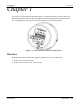
Introduction Overview Chapter 1 The iCon™ APX Advanced Functionality Meter is a commercial-grade, electricity meter. By analyzing information from the metering industry, Sensus Metering Systems has developed a new, configurable meter designed to meet the demands of commercial metering.
Manual Conventions Introduction Purpose The purpose of this manual is to provide: • • • Physical descriptions of the APX meters. Descriptions of fixed and optional features. A reference for meter set up, operation, troubleshooting, and maintenance. This document is intended for technically qualified personnel of energy supply companies and their contractors who are responsible for the system planning, installation, commissioning, operation, maintenance, decommissioning, and/or disposal of meters.
Introduction Manual Conventions Notational Conventions Hexadecimal Values Hexadecimal values in this manual are expressed as follows: • • Values that are in hexadecimal notation are shown as two or four (4) characters followed by the letter "h.” Each character can have a value from 0 through F. For example, 9C3Fh All other numbers are in decimal notation. Ranges Ranges, or parameters, expressed in this manual are expressed a pair of values separated by ellipses.
Manual Conventions Introduction Applicable Standards The iCon APX meter meets or exceeds the ANSI standards for commercial and industrial electricity metering. Table 1-1: Applicable Standards ANSI C12.1 – 2001 ANSI C12.13-1991 ANSI C12.18-1996 *ANSI C12.19 - 1997 *ANSI C12.20 – 2002 ANSI C12.21-1999 ANSI/IEEE C37.
Meter Overview iCon APX Meter Chapter 2 iCon APX Meter The iCon™ APX Advanced Functionality Meter continues to use same field-proven Sentec® sensor technology found in the other meters in the iCon family. Accuracy The APX meter is built with a backbone of precision that exceeds ANSI C12.20 standards for accuracy. Reliability The iCon APX meter uses a simple, unique modular design that meets the most stringent performance requirements for revenue billing applications.
System Architecture Meter Overview System Architecture Figure 2-1 shows the APX meter with the Meter Cover and Register Cover removed. Figure 2-1: APX Meter Internal Components APX meters: • • • Display accumulated electricity usage data on an easy-to-read liquid crystal display (LCD). Are compatible with industry requirements for mounting and device profile features. Are compliant with all applicable ANSI standards. NOTE: This manual describes some of the features available in iCon APX meters.
Meter Overview System Architecture Hardware The basic components of the meter are shown in Figure 2-2. Figure 2-2: iCon APX Meter Components Meter Base Assembly The Meter Base Assembly consists of the Meter Base, the Sensor Board, and related hardware. Figure 2-4 shows the Sensor Board in the Meter Base. There are no field-serviceable parts in the Meter Base Assembly. Figure 2-3: Meter Base Assembly Meter Base The Meter Base is molded from highly durable thermoplastics.
System Architecture Meter Overview Figure 2-4 through Figure 2-6 provide views of the available APX meter Forms. Figure 2-4 shows a transformer rated Form 9S (8S) Meter Base. Figure 2-4: Form 9S (8S) Meter Base Figure 2-4 shows a Form 16S (14S, 15S, 17S) Meter Base.
Meter Overview System Architecture For self-contained meters, there is an optional Phantom Load version of the Meter Base. Figure 2-6 shows a Form 15S/16S Meter Base with the Phantom Load (closed position). Figure 2-6: Form 15S/16S Meter Base - Optional Phantom Load All meter bases provide knockouts for the option boards. Figure 2-7: Meter Base – Option Board Knockouts Version 1.
System Architecture Meter Overview Sensor Board The Sensor Board is a part of the Meter Base Assembly and consists of the sensing circuitry, buss bars, power supply, and connector ports. There are no field serviceable components in the base assembly.
Meter Overview System Architecture Register Cover Assembly The Register Cover Assembly consists of: • • • • Register Cover Register Display Board Interconnect Board Option Boards Figure 2-8: Register Cover Assembly – Exploded View Version 1.
System Architecture Meter Overview Register Cover The Register Cover is an opaque shield that protects the meter’s internal components from external tampering and serves as the mounting surface for the labels. The cover also contains ‘pockets’ to house batteries that maintain the DC voltage for circuitry required to function during an outage; such as the RTC. Except for the Optical Port Shield, LCD, TEST tab, RESET tab, and ALT tab, no internal components can be viewed through the Register Cover.
Meter Overview • • • System Architecture Operating: ▪ Voltages ▪ Frequencies A unique meter identifier Descriptive information Meter information required by the utility • Factory-generated bar code for the: ▪ Meter ID ▪ Test board Warning Label The Warning Label contains a multi-lingual message on the hazards and potential consequences of working on energized equipment.
System Architecture Meter Overview Register Display Board The Register Display Board (display board) consists of a Liquid Crystal Display (LCD), Alternate Mode button, Demand Reset button, Test Mode button, three option-board connections, and an optical port consisting of one (1) infrared LED and one (1) infrared LED sensor.
Meter Overview System Architecture Liquid Crystal Display The LCD provides meter reading and test information. The information on the LCD is visible in direct sunlight and can be read at angles of 15 degrees above and below the LCD centerline. Figure 2-11 shows the LCD’s Annunciators and Displays. Figure 2-11: LCD Annunciators, Displays, and Indicators Annunciators Annunciators are composed of LCD segments that can be enabled/disabled to display the following meter conditions and measurements.
System Architecture Meter Overview M (Mega) — This Annunciator illuminates when the value shown by the Data Display is one million of a specified unit. k (kilo) — This Annunciator illuminates when the value shown by the Data Display is one thousand of a specified unit. V (Volts), W (Watts) — The W consists of two V-shaped Annunciators. When one Annunciator is illuminated, it appears as the letter V. When both Annunciators are illuminated, they appear as the letter W.
Meter Overview System Architecture Meters that do not have Reactive or Apparent energy measurements enabled will only be able to indicate the direction of the kWh energy. These meters will illuminate Quadrant 1 and Quadrant 4 to indicate energy flowing to a customer and Quadrant 2 and Quadrant 3 to indicate energy received from a customer. Data Display — The Data Display is composed of LCD segments that can display letters, digits, and symbols.
System Architecture Meter Overview Connector Ports The Register Display Board contains connector ports for option boards and the Interconnect Board. Figure 2-12 shows the locations of the connector ports. Figure 2-12: Register Display Board Connector Ports Interconnect Board The interconnect board provides a physical path for data and power supply signals from the Sensor Board in the Meter Base Assembly to the Register Display Board.
Meter Overview Metering Capabilities Figure 2-13: Meter Cover After final set-up and calibration of the meter at the factory, the Meter Cover and Meter Base Assembly are sealed with a T-Bar. The RESET/ALT Lever can also be sealed using an industry-standard Demand Reset Seal. Broken or missing seals provide evidence of possible tampering. Metering Capabilities The APX meter is capable of a wide range of measurements and calculations based on the needs of the customer.
Metering Capabilities Meter Overview Display Lists The meter maintains up to four (4) display lists. The contents of each list and the order in which items appear is configured using iConFig. Each list item is displayed as the meter scrolls through the list depending upon the meter’s operating Mode. Normal Display List When the meter is in Normal Mode, the Normal Display List is displayed.
Meter Overview Metering Capabilities Test Mode Lock This feature allows a utility to run special tests that require the meter to remain in Test Mode even after temporary interruptions in power. When the Test Mode Lock feature has been activated, the meter starts back up (i.e., after power is restored after an outage) in Test Mode provided it is still within its configured timeout period. To activate Test Mode Lock: 1. 2. 3. Ensure the meter is in Normal Mode.
Metering Capabilities Meter Overview While in Diagnostic Mode, the meter continues to measure and store usage data in the billing registers. After the configurable timeout period has expired, the meter automatically reverts back to the Normal Display List. To manually exit Diagnostic Mode, use the RESET/ALT Lever to press the ALT button. Alternatively, this mode can be entered and exited by way of remote commands using iConFig.
Operation Hardware Setup Chapter 3 The iCon™ APX Advanced Functionality Meter is configured using the iConFig™ application. This chapter provides brief descriptions of the Modules used to configure the meter. Refer to iConFig Start-up and User’s Guide for instructions on configuring the meter. Hardware Setup The information in this section is not intended to provide instructions to unqualified personnel nor replace the extensive training needed to safely handle the metering equipment.
Hardware Setup Operation Self-Contained Meters Some self-contained meters have Phantom Load links on the bottom of the Meter Base Assembly. Ensure the links are all up and secured with the screws. Figure 3-1: Phantom Load Links (closed) Calibration Check Do not permit unauthorized personnel to operate meter-testing equipment or to test meters. Hazardous voltages can be present, exposing personnel to the risk of death or serious injury, and exposing equipment to the risk of damage.
Operation Hardware Setup After completing the calibration check: 1. 2. Remove the meter from the test board. Close the Phantom Load links by: a. Loosening the lower screws on each link b. Sliding the links up until they stop 3. Securely tighten all of the screws to prevent the slides from moving. Testing To interface with test equipment, the meter generates test pulses. The energy value assigned to each test pulse is defined as the meter Kh and can be configured to value that is a multiple of 0.2.
Hardware Setup Operation IR Test Pulse LED Background The iCon APX meter contains a Metering Chip that is used for the measurement of energy (voltage * current). The test pulse signal is based on an output from this chip. This signal is routed up through the display board to the Infrared (IR) LED in the optical port on the face of the meter. The meter controls the function of the IR LED.
Operation Hardware Setup UTEC/RFL – Windows software 1. 2. 3. 4. 5. 6. 7. 8. 9. Enter Syslink DB Maintenance. Enter Meter Test under Testset Group. Select Testset. Edit SubTest. Enter Testpoint screen. Select Testpoint to edit. Change Stabilization Delay to 10 seconds. Save changes. If you have problems changing this in the UTEC software, call 800-952-8832. UTEC/RFL – DOS software The UTEC/RFL DOS software does not have a provision for a delay time.
Installation Operation Test Mode Operation While the meter is in Display Mode, the Test Pulse correlates to the energy value that is visible on the LCD. NOTE: If the Display List item does not have an energy reading, the Test Pulse will correlate to the kWh present at the meter. Example: If the item on the Display List is kWh delivered, the Test Pulse will correspond to the kWh presently going through the meter.
Operation Installation Diagnostics and Alarms” below. Meter Power-Up NOTE: If the meter was in Test Lock or the Test Mode timeout period had not expired, the LCD will display the last item that was shown on the LCD at the time power was removed. After installing the meter into a socket and applying power, the meter should boot up and start cycling through the Normal Display List unless: • • The meter was powered down while in Test Lock The Test Mode Timeout Period has not expired.
Configuring APX Meters Operation Configuring APX Meters With iConFig, users can create or edit configuration programs that can be downloaded into APX meters. iConFig is a user-friendly software package that has been developed to configure, troubleshoot, and read the APX meter. iConFig is designed to be a flexible, Microsoft® Windows-based application that runs on: Windows: • • • • • 98SE NT 4.
Operation Configuring APX Meters Identification The Identification data contains information about the utility, the configuration program, vendor, and other meter data. The data in this Module is for informational purposes and has no effect on the operation of the meter. The following identification data are permanently stored in meter memory. The data is stored at the factory and no changes are allowed.
Configuring APX Meters Operation Diagnostics and Alarms The meter can be configured to monitor or ignore certain internal conditions and to display alarm codes should any of those condition be detected.
Operation Configuring APX Meters History Logs In addition to recording Diagnostic and Alarm events, the meter can record other events (e.g., outages, downloading configuration program, entering/exiting Test Mode). For Time-of-Use and Load Profile meters that have the Calendar function enabled, the time and date each event occurs is also stored. History Logs allow the meter to record Events that occur during the normal operation of the meter.
Servicing the iCon APX Meter Meter Communication Chapter 4 This section provides brief descriptions and procedures for: • • • • Communicating with the meter Programming the meter (firmware) Resetting the meter Replacing meter components Meter Communication Linking with meter is accomplished by various means. This section provides brief descriptions of the means to communicate with APX meters for data transfer, programming and configuring, and meter updates.
Troubleshooting Servicing the iCon APX Meter NOTE: Performing a Cold Start clears all of the customer data registers. Ensure all customer data is downloaded and stored prior to performing a Cold Start. Failure to observe this note will result in permanent data loss. A Cold Start restores the meter to factory default settings. All configuration settings as well as billing, status, and history data will be lost. Some meters come from the factory pre-programmed and performing a Cold Start is not required.
Servicing the iCon APX Meter Troubleshooting Installation Check The most common cause of incorrect data registration is incorrect installation or the installation of the meter in an application other than its intended application.
Replacement – Basic Components Servicing the iCon APX Meter A unique error code can be displayed on the LCD for each Diagnostic Check failure. Refer to Appendix C: Alarms, Diagnostics, and Errors for more information on specific error codes and corrective measures.
Servicing the iCon APX Meter Replacement – Basic Components Replacement of the Meter Cover It is strongly recommended that all replacement procedures for component-level repairs be done in the shop. Removal of the Meter Cover in the field may allow debris or other contaminants into the meter, damaging the meter or causing further damage to a malfunctioning meter.
Replacement – Basic Components Servicing the iCon APX Meter Installing the Meter Cover 1. 2. Reseat the Meter Cover into the Meter Base Assembly Turn the Meter Cover clockwise until it reaches a positive stop. Figure 4-2: Installing the Meter Cover 3. 4. Install a new T-Bar Seal. Install a new Demand Reset Seal. Replacement of the Register Cover The instructions in this section provide the necessary steps required to replace the Register Cover.
Servicing the iCon APX Meter Replacement – Basic Components Removing the Register Cover 1. 2. Remove the Meter Cover. Refer to “Removing the Meter Cover” above. Loosen the three (3) captive screws that secure the Register Cover to the Meter Base Assembly so they are no longer engaged in the Base Assembly. Figure 4-3: Register Cover – Captive Screws The APX meter design provides a secure fit of the Interconnect Board into the Sensor Board connector port.
Replacement – Basic Components Servicing the iCon APX Meter Installing the Register Cover 1. 2. 3. Hold the Register Cover at a slight angle as shown in Figure 4-5. Align the Interconnect Board with the associated connector on the Sensor Board. Align the Captive Screw Slot with the opening in the Sensor Board. Figure 4-5: Installing the Register Cover 4. 5.
Servicing the iCon APX Meter Replacement – Basic Components Replacing the Interconnect Board This section provides the instructions necessary to replace the Interconnect Board. Removing the Interconnect Board 1. Remove the Register Cover. Refer to “Removing the Register Cover” above. The Register Display Board and Register Cover may contain sharp edges. Exercise care while removing the Interconnect Board. Do not overextend the Integrated Alignment Ribs.
Replacement – Basic Components Servicing the iCon APX Meter Installing the Interconnect Board 1. Slide the Interconnect Board into the Integrated Alignment Ribs. Figure 4-7: Installing the Interconnect Board 2. Align the Header Pins on the Interconnect Board with the connector on the Register Display Board. The Register Display Board, Register Cover, and Interconnect Board may contain sharp edges. Exercise care while installing the Interconnect Board.
Servicing the iCon APX Meter Replacement – Basic Components Replacing the Register Display Board This section contains instructions for replacing the Register Display Board. Removing the Register Display Board 1. 2. Remove the Interconnect Board. Refer to “Removing the Interconnect Board” above. Remove the screws securing the Register Display Board to the Register Cover. Figure 4-8: Removing the Register Display Board 3. Version 1.0 Carefully lift the display board out of the Register Cover.
Replacement – Basic Components Servicing the iCon APX Meter Installing the Register Display Board 1. 2. Align the LCD with the rectangular opening in the Register Cover. Insert the Register Display Board into the Meter Base Assembly as shown in Figure 4-9.
Servicing the iCon APX Meter 3. 4. Replacement – Basic Components Locate the four (4) holes for the screws. Secure the display board to the Register Cover using the four (4) screws. Figure 4-10: Installing the Register Display Board Screws 5. 6. Install the Interconnect Board. Refer to “Installing the Interconnect Board” above. Install the Register Cover. Refer to “Installing the Register Cover” above.
Theory of Operation Metrology Chapter 5 This chapter describes the theory of operation for the iCon™ APX Advanced Functionality meter. Figure 5-1 supplements the information contained in this section. Figure 5-1: APX Meter Operational Overview Metrology The APX meter performs certain operations on the power present at the socket to provide accurate measurements.
Metrology Theory of Operation Voltage Sensor Voltage on each phase is measured using a precision-resistive-divider that is designed to maintain a highly stable division ratio over temperature, humidity, and time. The signals from the divider feed into the Metering Chip.
Theory of Operation Register Display Board kVA/kVAR Calculations The Metering Chip calculates a +90 degree, phase-shifted current signal. The result is multiplied by the voltage signal to calculate reactive power (kVAR). The accumulation of reactive power over time provides the reactive energy (kVARh) measurement. The Metering Chip measures the instantaneous RMS current and voltage signals and multiplies them together to create apparent power (arithmetic) samples.
Power Supply Theory of Operation Non-Volatile Memory Special algorithms have been employed to ensure the long-term validity of the data stored in 256 KB of flash memory. This memory is used to store all non-volatile data such as: • • • • Meter configuration (iConFig created meter Program) Billing data Load Profile data Status data Power Supply The power supply is a wide-range, switch-mode supply that is designed to operate from a poly-phase supply.
Theory of Operation Demand Metering Sliding Sliding (Rolling) Demand is where intervals are divided into a fixed number of subintervals. Demand calculations are performed at the end of each subinterval instead of at the end of each interval. As in Block Demand, the interval length must be a factor of 60. The subinterval length must be a factor of the interval. Figure 5-2 is an example of an interval of 30 minutes with 10-minute subintervals.
Demand Metering Theory of Operation Outage Recognition The meter can detect temporary interruptions in service. For Demand calculations, meters without Real-Time-Clocks (RTCs) “recognize” all interruptions in service as outages. Meters with RTCs can be configured to only “recognize” outages if they last more than the configured number of seconds. The Outage Recognition Time is configurable using iConFig.
Socket Wiring Form 8S Appendix A This appendix provides meter and ANSI compliant socket specifications. Form 8S The standard connections for the iCon™ APX Advanced Functionality Meter are made with blades that pass through the Meter Base into ANSI compliant sockets. Figure A-1 shows the socket wiring for a two-element, transformer-rated, three-phase, four-wire socket for Delta service connections.
Form 14S Socket Wiring Form 14S Figure A-3 shows the socket wiring for a two-element, self-contained, three-phase, four-wire socket for Wye service connections. Figure A-3: Socket Wiring - Form 14S Form 15S Figure A-4 shows the socket wiring for a two-element, self-contained, three-phase, four-wire socket for Delta service connections.
Socket Wiring Form 17S Form 17S Figure A-6 shows the socket wiring for a three-element, self-contained, three-phase, four-wire socket for Delta service connections. Figure A-6: Socket Wiring - Form 17S Version 1.
Specifications Meter Specifications Appendix B This appendix provides meter and ANSI compliant socket specifications.
Meter Specifications Specifications Input Table B-4: Input Specifications Starting Current 5mA for Class 20 * Power Supply Burden 50mA for Class 200 120V 2.2W 3.5VA 240V Current Circuit Burden * 2.8W 6.6VA 277V 2.4W 6.8VA < 0.25 VA per phase at Test Amperes - Input voltage measured phase to Neutral. Physical Dimensions Dimensions in cm A B 6.45 6.95 C D E F G 5.0 0.91 0.27 0.55 3.31 16.38 17.65 12.80 2.31 0.69 1.40 8.41 Shipping Weight B-2 Specifications 1 Meter Carton 2.
Alarms, Diagnostics, and Errors Codes Appendix C The tables in this appendix outline the codes for alarms and errors within the meter. Many of the codes can be configured by iConFig™ to be displayed on the meter’s LCD should certain conditions or events occur. Refer to iConFig Set-up and User’s Guide for configurable alarms and thresholds. Certain conditions are detected by the meter and may be accompanied by one or more codes that aid the technician in troubleshooting the situation.
Codes Alarms, Diagnostics, and Errors Alarm Codes Description 0008 Unprogrammed 0013 Non-Volatile Memory Error 0014 RTC Error 0016 Low Battery 0021 Reverse Rotation Detected (poly-phase) 0072 Register Overflow 0073 Last Demand Interval Restore Failed 0074 Last Load Profile Interval Restore Failed 0075 Modem Error 0080 0088 0089 0090 0091 0092 0093 0096 0097 0098 0099 0100 0101 0104 0106 0107 0108 0109 Calibration Error – E2 Corrupt Demand Overload Tier A Demand Overload Tier B Demand
Alarms, Diagnostics, and Errors Alarm Codes - continued Codes Description 0112 0113 0114 0115 0116 0117 0118 0119 0120 0121 0122 0123 0124 0125 0126 0127 0128 0129 0130 0131 0132 0133 0134 0135 0136 0137 0138 0139 0140 0141 0142 0143 Low Current Phase A Low Current Phase B Low Current Phase C Low Current (System) High Current Phase A High Current Phase B High Current Phase C High Current (System) Low Voltage Phase A Low Voltage Phase B Low Voltage Phase C Low Voltage (System) High Current Phase A High Volt
Codes Alarms, Diagnostics, and Errors Diagnostic These diagnostics can turned On or Off with iConFig. The diagnostics are designed to assist the technicians and installers in diagnosing any error conditions within the meter and the service at the socket.
Alarms, Diagnostics, and Errors Codes Error Codes - continued Codes 9101 9102 9103 9104 9111 9201 9202 9203 9306 9307 930A 9601 9602 9603 9604 9605 9606 9607 9608 9609 960A 960B 960C 960D 960E 960F 9640 9641 9642 9643 9644 9645 9646 9647 9648 9649 964A 964B 964C 964D 964E 9650 9651 9652 9653 9655 9656 Version 1.
Index Index 1 120, 277, 240, 480 Indicators, 2-12 A Activating Test Mode Lock, 2-17 ADE7758 Integrated IC Chip, 2-6 Alarm Codes, C-2 ALT Button, 3-5 ALT Tab, 2-8 Alternate Display List, 2-16 Alternate Mode Button, 2-10, 2-13 Annunciators, 2-11, 2-12 ANSI Standards, 1-4 B Billing Registers, 1-3 Block Interval Demand, 5-4 Buss Bars, 2-6 Buttons ALT, 3-5 Alternate Mode, 2-10, 2-13 Demand Reset, 2-10, 2-13 RESET, 3-6, 4-4 TEST, 3-5, 3-6 Test Mode, 2-10, 2-13 C Calculations kVA, 5-3 kVAR, 5-3 Watt Hours, 5-2
Index Error! No text of specified style in document.
Index M Maximums, B-1 Meter Base Assembly, 2-3, 3-2 Meter Communication, 4-1 Meter Configuration, 3-8 Meter Cover, 2-14 Installing, 4-6 Removing, 4-5 Meter Hardware, 2-3 ADE7758 Integrated IC Chip, 2-6 Buss Bars, 2-6 Connector Ports, 2-6, 2-14 Infrared LED, 2-10 Infrared LED Sensor, 2-10 Interconnect Board, 2-14 Knockouts, 2-5 LCD, 2-11 LCD Annunciators, 2-11 LCD Displays, 2-11 LCD Indicators, 2-11 Meter Base, 2-3 Meter Base Assembly, 2-3, 3-2 Form 15S/16S, 2-5 Form 16S (14S, 15S, 17S), 2-4 Form 9S (8S), 2
Index Error! No text of specified style in document.
Index T Tabs ALT, 2-8 RESET, 2-8 TEST, 2-8 T-Bar Seal, 2-3, 3-1 Tempratures, B-1 TEST Button, 3-5, 3-6 Test Display List, 2-16 Test Lock, 3-6 Test Mode, 3-5 Button, 2-10, 2-13 Demand Interval, 2-15 Demand Subinterval, 2-15 Display List, 3-5 Registers, 3-6 Test Mode Lock, 2-17 Activating, 2-17 Exiting, 2-17 Test Pulse, 3-6 Test Pulse Kh Outputs, 3-3, 4-3 Test Pulses, 3-3 TEST Tab, 2-8 Theory of Opearation Block Interval Demand, 5-4 Theory of Operation, 5-1 Demand, 5-4 Power Supply, 5-4 Register Display Boar
Sensus Metering Systems 1501 Ardmore Boulevard, Suite 600 Pittsburgh, PA 15221 USA 1-800-METER-IT (638 - 3748) 1-800-888-2403 (fax) www.sensus.com TM-iX0A-0805 1.