
User Manual


Table Of Contents
- Table of Contents
- 1 Introduction
- 2 SmartPoint Module Overview
- 3 On Air Message Format
- 4 On Air Message Types
- 4.1 On Air Message Types
- 4.2 Testing Message – App Code 220
- 4.3 Meter Setup / Configuration Message—App Code 1
- 4.4 Meter Serial Number/Position Binding—App Code 5
- 4.5 GPS Mapping Message
- 4.6 Command Message—App Code 7
- 4.7 Buddy Message—App Code 8
- 4.8 C&I Meter Read With History—App Code 13
- 4.9 C&I Tier Data—App Code 14
- 4.9.1 Message Format
- 4.9.2 Tier Information
- 4.9.3 Meter Type
- 4.9.4 Selected Data Table
- 4.9.5 Data Flags / Peak Demand Time
- 4.9.6 Summation Reading (103 resolution)
- 4.9.7 Demand Reading (100 resolution)
- 4.9.8 Cumulative Demand Reading (103 resolution)
- 4.9.9 Coincident Reading (103 resolution)
- 4.9.10 # Demand Resets
- 4.9.11 Source Indices
- 4.9.12 Quantity of Tier Information
- 4.9.13 Service Quality Message Format
- 4.10 C&I Tunneling Read—App Code 15
- 4.11 C&I Alarm Message – App Code 16
- 4.11.1 Application Data
- 4.11.2 Voltage Phase A,B, and C
- 4.11.3 Click Count
- 4.11.4 Time Since Event
- 4.11.5 Current Meter Reading
- 4.11.6 Extended Time Since Event
- 4.11.7 Device Temperature
- 4.11.8 µP Status
- 4.11.9 Lock Errors
- 4.11.10 Alarm Data
- 4.11.11 Time of Last Power Failure
- 4.11.12 Total # of Outages
- 4.11.13 Flags
- 4.12 Demand History Message—App Code 25
- 4.12.1 Message Format
- 4.12.2 Number of Demand Resets
- 4.12.3 Last Demand Reset Date and Time
- 4.12.4 Last Peak Demand Date and Time
- 4.12.5 Last Peak Demand
- 4.12.6 Last Consumption Reading
- 4.12.7 2nd Demand Reset Date and Time
- 4.12.8 2nd Peak Demand Date and Time
- 4.12.9 2nd Peak Demand
- 4.12.10 2nd Consumption Reading
- 4.13 Load Profile Metadata Message—App Code 28
- 4.14 Load Profile Block Data Message—App Code 29
- 4.15 Firmware Image Check Response—App Code 30
- 4.16 High Res C&I Meter Read with History—App Code 38
- 4.17 Generic Ping Response—App Code 48
- 4.18 C&I High Res Read with History Data—App Code 55
- 4.19 Scratch Pad Image Check Response—App Code 57
- 5 Setup and Configuration
- 5.1 Electrical Configuration Interface
- 5.2 Configurable Parameters
- 5.2.1 End Point ID
- 5.2.2 Meter Sample Rate
- 5.2.3 Supervisory Transmit Rate
- 5.2.4 Base Frequency Channel
- 5.2.5 Transmit Frequency Channels
- 5.2.6 Receive Frequency Channel
- 5.2.7 C&I Mode Channel
- 5.2.8 Priority Mode Channel
- 5.2.9 Transmit Channel Mask
- 5.2.10 Transmit Operational Mode
- 5.2.11 Receiver Operational Mode
- 5.2.12 Enable Encryption
- 5.2.13 Programmer ID
- 5.3 Setup Messages
- 5.4 Status Request (0x91)
- 5.5 Set Device ID (0x92)
- 5.6 Device Static Setup
- 5.7 Set TCXO Correction (0x94)
- 5.8 Set Latitude/Longitude (0x95)
- 5.9 Set A/D Calibration (0x96)
- 5.10 Set Voltage Quality Thresholds (0x97)
- 5.11 Set Encryption Key (0x98)
- 5.12 Set Real Time Clock (0x99)
- 5.13 Send Data (0x9A)
- 5.14 Ping (0x9C)
- 5.15 Set Customer Meter Number (0x9D)
- 5.16 Set Customer ID (0x9E)
- 5.17 Send Data Commands
- 6 Receiver Section
- 6.1 Receiver Requirements
- 6.2 Receiver On Air Command Messages
- 6.2.1 Command Types
- 6.2.2 Command Acknowledge
- 6.2.3 Set Static Setup
- 6.2.4 Set TCXO Correction
- 6.2.5 Set Latitude and Longitude
- 6.2.6 Set VoltVoltage Quality settings:
- 6.2.7 Set
- 6.2.8 On Demand Read / Drive By Read
- 6.2.9 Ping
- 6.2.10 Set Transmitter Id
- 6.2.11 Set Customer Id
- 6.2.12 Set Encryption Key
- 6.2.13 Set Preferred Buddy Id
- 6.2.14 Set Company Meter Number
- 6.2.15 C&I Read C12.19 Data
- 6.2.16 C&I Write C12.19 Data
- 6.2.17 C&I Demand Reset
- 6.3 Command Addressing
- 6.4 Receiver Miscellaneous
- Appendix A FlexNet SmartPoint Radio Overview
- Appendix B Specifications
- Index
Setup and Configuration 5-2
SmartPoint Module for the Elster A3 Meter ECMTM40000
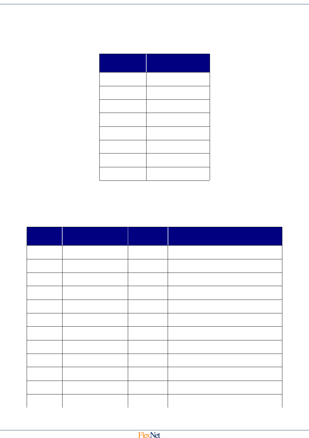
5.2.2 Meter Sample Rate
The 3-bit field indicating how often the meter is read using the Elster interface. The meter is sampled
without dither and is synchronized to the top of the hour by a real-time clock. The field is defined as
shown in the table below (6-7 are reserved):
5.2.3 Supervisory Transmit Rate
The 5-bit field indicating how often RF messages are autonomously transmitted. RF Transmissions
are randomly dithered in time from 0 to +/- 20% in time in order to avoid repetitive on-air collisions by
different end-point devices. The field is defined as shown in the table below:
Field Value
Meter Sample
Rate
0 5 minutes
115 minutes
2 1 hour
3 6 hours
4 12 hours
5 24 hours
6 Reserved
7 Factory Sleep
Field
Value
Supervisory
Transmit Rate
20%
Variation
Total Range
0 1 minute 12 sec 48 – 72 sec
1 5 minutes 1 min 4 – 6 min
2 15 minutes 3 min 12 – 18 min
3 30 minutes 6 min 24 – 36 min
4 45 minutes 9 min 36 – 54 min
5 1 hour 12 min 48 - 72 min
6 1.5 hours 18 min 72 – 108 min
7 2 hours 24 min 96 – 144 min
8 2.5 hours 30 min 120 – 180 min
9 3 hours 36 min 144 – 216 min
10 3.5 hours 42 min 168 – 252 min
11 4 hours 48 min 192 – 288 min