
User Manual


Table Of Contents
- Table of Contents
- 1 Introduction
- 2 SmartPoint Module Overview
- 3 On Air Message Format
- 4 On Air Message Types
- 4.1 On Air Message Types
- 4.2 Testing Message – App Code 220
- 4.3 Meter Setup / Configuration Message—App Code 1
- 4.4 Meter Serial Number/Position Binding—App Code 5
- 4.5 GPS Mapping Message
- 4.6 Command Message—App Code 7
- 4.7 Buddy Message—App Code 8
- 4.8 C&I Meter Read With History—App Code 13
- 4.9 C&I Tier Data—App Code 14
- 4.9.1 Message Format
- 4.9.2 Tier Information
- 4.9.3 Meter Type
- 4.9.4 Selected Data Table
- 4.9.5 Data Flags / Peak Demand Time
- 4.9.6 Summation Reading (103 resolution)
- 4.9.7 Demand Reading (100 resolution)
- 4.9.8 Cumulative Demand Reading (103 resolution)
- 4.9.9 Coincident Reading (103 resolution)
- 4.9.10 # Demand Resets
- 4.9.11 Source Indices
- 4.9.12 Quantity of Tier Information
- 4.9.13 Service Quality Message Format
- 4.10 C&I Tunneling Read—App Code 15
- 4.11 C&I Alarm Message – App Code 16
- 4.11.1 Application Data
- 4.11.2 Voltage Phase A,B, and C
- 4.11.3 Click Count
- 4.11.4 Time Since Event
- 4.11.5 Current Meter Reading
- 4.11.6 Extended Time Since Event
- 4.11.7 Device Temperature
- 4.11.8 µP Status
- 4.11.9 Lock Errors
- 4.11.10 Alarm Data
- 4.11.11 Time of Last Power Failure
- 4.11.12 Total # of Outages
- 4.11.13 Flags
- 4.12 Demand History Message—App Code 25
- 4.12.1 Message Format
- 4.12.2 Number of Demand Resets
- 4.12.3 Last Demand Reset Date and Time
- 4.12.4 Last Peak Demand Date and Time
- 4.12.5 Last Peak Demand
- 4.12.6 Last Consumption Reading
- 4.12.7 2nd Demand Reset Date and Time
- 4.12.8 2nd Peak Demand Date and Time
- 4.12.9 2nd Peak Demand
- 4.12.10 2nd Consumption Reading
- 4.13 Load Profile Metadata Message—App Code 28
- 4.14 Load Profile Block Data Message—App Code 29
- 4.15 Firmware Image Check Response—App Code 30
- 4.16 High Res C&I Meter Read with History—App Code 38
- 4.17 Generic Ping Response—App Code 48
- 4.18 C&I High Res Read with History Data—App Code 55
- 4.19 Scratch Pad Image Check Response—App Code 57
- 5 Setup and Configuration
- 5.1 Electrical Configuration Interface
- 5.2 Configurable Parameters
- 5.2.1 End Point ID
- 5.2.2 Meter Sample Rate
- 5.2.3 Supervisory Transmit Rate
- 5.2.4 Base Frequency Channel
- 5.2.5 Transmit Frequency Channels
- 5.2.6 Receive Frequency Channel
- 5.2.7 C&I Mode Channel
- 5.2.8 Priority Mode Channel
- 5.2.9 Transmit Channel Mask
- 5.2.10 Transmit Operational Mode
- 5.2.11 Receiver Operational Mode
- 5.2.12 Enable Encryption
- 5.2.13 Programmer ID
- 5.3 Setup Messages
- 5.4 Status Request (0x91)
- 5.5 Set Device ID (0x92)
- 5.6 Device Static Setup
- 5.7 Set TCXO Correction (0x94)
- 5.8 Set Latitude/Longitude (0x95)
- 5.9 Set A/D Calibration (0x96)
- 5.10 Set Voltage Quality Thresholds (0x97)
- 5.11 Set Encryption Key (0x98)
- 5.12 Set Real Time Clock (0x99)
- 5.13 Send Data (0x9A)
- 5.14 Ping (0x9C)
- 5.15 Set Customer Meter Number (0x9D)
- 5.16 Set Customer ID (0x9E)
- 5.17 Send Data Commands
- 6 Receiver Section
- 6.1 Receiver Requirements
- 6.2 Receiver On Air Command Messages
- 6.2.1 Command Types
- 6.2.2 Command Acknowledge
- 6.2.3 Set Static Setup
- 6.2.4 Set TCXO Correction
- 6.2.5 Set Latitude and Longitude
- 6.2.6 Set VoltVoltage Quality settings:
- 6.2.7 Set
- 6.2.8 On Demand Read / Drive By Read
- 6.2.9 Ping
- 6.2.10 Set Transmitter Id
- 6.2.11 Set Customer Id
- 6.2.12 Set Encryption Key
- 6.2.13 Set Preferred Buddy Id
- 6.2.14 Set Company Meter Number
- 6.2.15 C&I Read C12.19 Data
- 6.2.16 C&I Write C12.19 Data
- 6.2.17 C&I Demand Reset
- 6.3 Command Addressing
- 6.4 Receiver Miscellaneous
- Appendix A FlexNet SmartPoint Radio Overview
- Appendix B Specifications
- Index
On Air Message Types 4-8
SmartPoint Module for the Elster A3 Meter ECMTM40000
4.8 C&I Meter Read With History—App Code 13
4.8.1 Message Format
This is the standard meter reading message and has the following format:
4.8.2 Relative Time Stamp
16 bits of byte 0-1, elapsed time since last meter reading. Time is always represented in two-second
resolution.
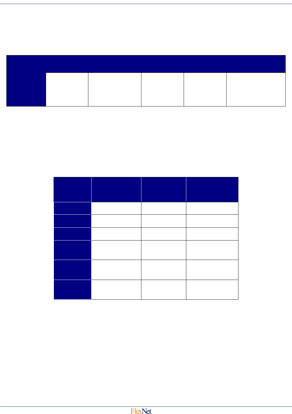
4.8.3 Delta Data Type
3 bits, bits 0-2 of byte 2. Used to define the amount of time represented by each History Sample in
bytes 8-27. The valid values for Delta Data Type are defined in the table below.
4.8.4 Compression Enabled
1 bit, bit 3 of byte 2. If set, the History Sample in bytes 8-27 are sent in the data compression enabled
format. If cleared, the History sample bytes are sent in the fixed bin width format.
4.8.5 Current Meter Reading
20 bits, bits 4-7 of byte 2 and all of bytes 3 and 4. The total power consumption represented in binary
in kWh.
App Data
Byte
0-1 2-4 5-8 9-11 12-27
Data
Relative
Time
Stamp
Delta Data
Type / Current
Reading
Peak
Demand
Reading
Phase A,
Phase B,
Phase C
Voltage
History Samples
Delta
Data
Type
History
Samp
Interval (min)
Max Pulses
per Interval
Likely
Transmit
Rate
0
5 28.33 30 min
1
15 85.00 1 Hr
2
60 340.00 4 Hr
3
360
(6 Hours)
2040.00 6 Hr
4
720
(12 Hours)
4080.00 12 Hr
5
1440
(24 Hours)
8160.00 12 Hr