
User Manual


Table Of Contents
- Table of Contents
- 1 Introduction
- 2 SmartPoint Module Overview
- 3 On Air Message Format
- 4 On Air Message Types
- 4.1 On Air Message Types
- 4.2 Testing Message – App Code 220
- 4.3 Meter Setup / Configuration Message—App Code 1
- 4.4 Meter Serial Number/Position Binding—App Code 5
- 4.5 GPS Mapping Message
- 4.6 Command Message—App Code 7
- 4.7 Buddy Message—App Code 8
- 4.8 C&I Meter Read With History—App Code 13
- 4.9 C&I Tier Data—App Code 14
- 4.9.1 Message Format
- 4.9.2 Tier Information
- 4.9.3 Meter Type
- 4.9.4 Selected Data Table
- 4.9.5 Data Flags / Peak Demand Time
- 4.9.6 Summation Reading (103 resolution)
- 4.9.7 Demand Reading (100 resolution)
- 4.9.8 Cumulative Demand Reading (103 resolution)
- 4.9.9 Coincident Reading (103 resolution)
- 4.9.10 # Demand Resets
- 4.9.11 Source Indices
- 4.9.12 Quantity of Tier Information
- 4.9.13 Service Quality Message Format
- 4.10 C&I Tunneling Read—App Code 15
- 4.11 C&I Alarm Message – App Code 16
- 4.11.1 Application Data
- 4.11.2 Voltage Phase A,B, and C
- 4.11.3 Click Count
- 4.11.4 Time Since Event
- 4.11.5 Current Meter Reading
- 4.11.6 Extended Time Since Event
- 4.11.7 Device Temperature
- 4.11.8 µP Status
- 4.11.9 Lock Errors
- 4.11.10 Alarm Data
- 4.11.11 Time of Last Power Failure
- 4.11.12 Total # of Outages
- 4.11.13 Flags
- 4.12 Demand History Message—App Code 25
- 4.12.1 Message Format
- 4.12.2 Number of Demand Resets
- 4.12.3 Last Demand Reset Date and Time
- 4.12.4 Last Peak Demand Date and Time
- 4.12.5 Last Peak Demand
- 4.12.6 Last Consumption Reading
- 4.12.7 2nd Demand Reset Date and Time
- 4.12.8 2nd Peak Demand Date and Time
- 4.12.9 2nd Peak Demand
- 4.12.10 2nd Consumption Reading
- 4.13 Load Profile Metadata Message—App Code 28
- 4.14 Load Profile Block Data Message—App Code 29
- 4.15 Firmware Image Check Response—App Code 30
- 4.16 High Res C&I Meter Read with History—App Code 38
- 4.17 Generic Ping Response—App Code 48
- 4.18 C&I High Res Read with History Data—App Code 55
- 4.19 Scratch Pad Image Check Response—App Code 57
- 5 Setup and Configuration
- 5.1 Electrical Configuration Interface
- 5.2 Configurable Parameters
- 5.2.1 End Point ID
- 5.2.2 Meter Sample Rate
- 5.2.3 Supervisory Transmit Rate
- 5.2.4 Base Frequency Channel
- 5.2.5 Transmit Frequency Channels
- 5.2.6 Receive Frequency Channel
- 5.2.7 C&I Mode Channel
- 5.2.8 Priority Mode Channel
- 5.2.9 Transmit Channel Mask
- 5.2.10 Transmit Operational Mode
- 5.2.11 Receiver Operational Mode
- 5.2.12 Enable Encryption
- 5.2.13 Programmer ID
- 5.3 Setup Messages
- 5.4 Status Request (0x91)
- 5.5 Set Device ID (0x92)
- 5.6 Device Static Setup
- 5.7 Set TCXO Correction (0x94)
- 5.8 Set Latitude/Longitude (0x95)
- 5.9 Set A/D Calibration (0x96)
- 5.10 Set Voltage Quality Thresholds (0x97)
- 5.11 Set Encryption Key (0x98)
- 5.12 Set Real Time Clock (0x99)
- 5.13 Send Data (0x9A)
- 5.14 Ping (0x9C)
- 5.15 Set Customer Meter Number (0x9D)
- 5.16 Set Customer ID (0x9E)
- 5.17 Send Data Commands
- 6 Receiver Section
- 6.1 Receiver Requirements
- 6.2 Receiver On Air Command Messages
- 6.2.1 Command Types
- 6.2.2 Command Acknowledge
- 6.2.3 Set Static Setup
- 6.2.4 Set TCXO Correction
- 6.2.5 Set Latitude and Longitude
- 6.2.6 Set VoltVoltage Quality settings:
- 6.2.7 Set
- 6.2.8 On Demand Read / Drive By Read
- 6.2.9 Ping
- 6.2.10 Set Transmitter Id
- 6.2.11 Set Customer Id
- 6.2.12 Set Encryption Key
- 6.2.13 Set Preferred Buddy Id
- 6.2.14 Set Company Meter Number
- 6.2.15 C&I Read C12.19 Data
- 6.2.16 C&I Write C12.19 Data
- 6.2.17 C&I Demand Reset
- 6.3 Command Addressing
- 6.4 Receiver Miscellaneous
- Appendix A FlexNet SmartPoint Radio Overview
- Appendix B Specifications
- Index
On Air Message Types 4-3
SmartPoint Module for the Elster A3 Meter ECMTM40000
Specific definitions for these fields are shown in Chapter 5, with the exception of the first two fields, Firmware
Version and Device Type. Firmware version contains the version of the firmware of the device. If the most
significant bit of Firmware version is set, the firmware is a beta test set.
The Device Type is currently defined as Device Type 5.
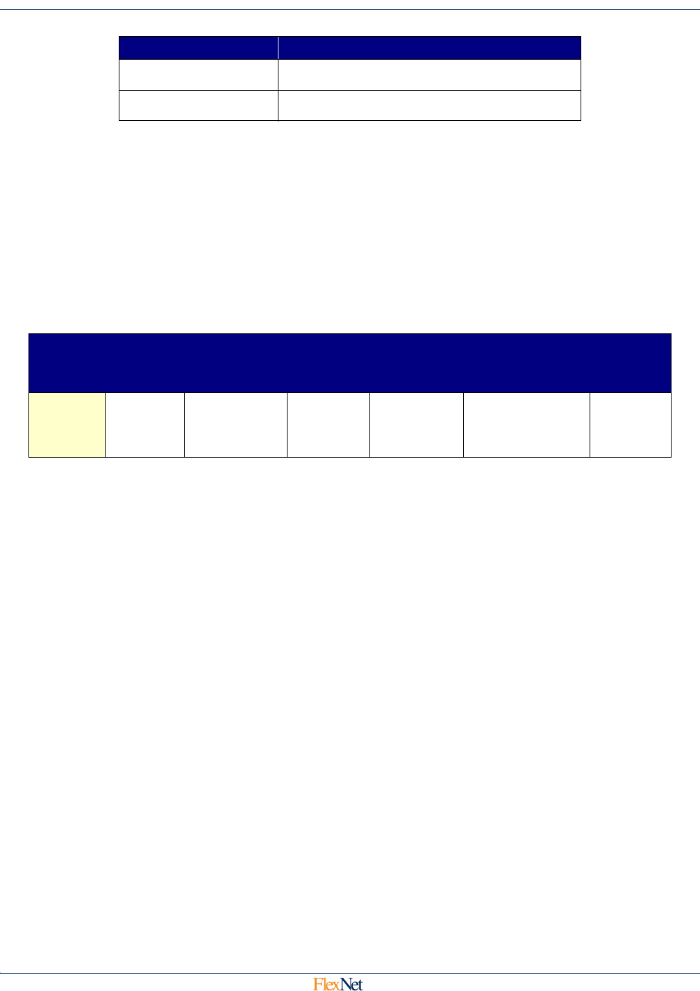
4.4 Meter Serial Number/Position Binding—App Code 5
4.4.1 Message Format
This message contains the meter Serial Number and also the installation latitude and longitude (if
position is programmed in at installation time). The message has the following format.
4.4.2 Status Flags
Only bit 0 is currently used and is the Just Programmed Bit. It is set if the device has received a static
setup in the last 5 minutes. The remaining bits are (reserved) and are set to 0.
4.4.3 Meter Serial Number
A 13 byte field containing the ASCII Serial Number reported by the end point device’s associated
meter display board.
4.4.4 Latitude / Longitude
These fields contain a floating point representation in degrees of the end point device’s installation
latitude and longitude. These fields are set using the installer with the installation tool, the end point
has no on board GPS capability.
27 (0:3) Outage Time Threshold
27 (4:7) Restored Time Threshold
App
Data
Byte
0 1-13 14-17 18-21 22-23 24
Data
Status
Flags
Meter
Serial
Number
Latitude Longitude
Programmer
ID
Setup
Flags
Byte (Bits) Field