
User Manual


Table Of Contents
- Table of Contents
- 1 Introduction
- 2 SmartPoint Module Overview
- 3 On Air Message Format
- 4 On Air Message Types
- 4.1 On Air Message Types
- 4.2 Testing Message – App Code 220
- 4.3 Meter Setup / Configuration Message—App Code 1
- 4.4 Meter Serial Number/Position Binding—App Code 5
- 4.5 GPS Mapping Message
- 4.6 Command Message—App Code 7
- 4.7 Buddy Message—App Code 8
- 4.8 C&I Meter Read With History—App Code 13
- 4.9 C&I Tier Data—App Code 14
- 4.9.1 Message Format
- 4.9.2 Tier Information
- 4.9.3 Meter Type
- 4.9.4 Selected Data Table
- 4.9.5 Data Flags / Peak Demand Time
- 4.9.6 Summation Reading (103 resolution)
- 4.9.7 Demand Reading (100 resolution)
- 4.9.8 Cumulative Demand Reading (103 resolution)
- 4.9.9 Coincident Reading (103 resolution)
- 4.9.10 # Demand Resets
- 4.9.11 Source Indices
- 4.9.12 Quantity of Tier Information
- 4.9.13 Service Quality Message Format
- 4.10 C&I Tunneling Read—App Code 15
- 4.11 C&I Alarm Message – App Code 16
- 4.11.1 Application Data
- 4.11.2 Voltage Phase A,B, and C
- 4.11.3 Click Count
- 4.11.4 Time Since Event
- 4.11.5 Current Meter Reading
- 4.11.6 Extended Time Since Event
- 4.11.7 Device Temperature
- 4.11.8 µP Status
- 4.11.9 Lock Errors
- 4.11.10 Alarm Data
- 4.11.11 Time of Last Power Failure
- 4.11.12 Total # of Outages
- 4.11.13 Flags
- 4.12 Demand History Message—App Code 25
- 4.12.1 Message Format
- 4.12.2 Number of Demand Resets
- 4.12.3 Last Demand Reset Date and Time
- 4.12.4 Last Peak Demand Date and Time
- 4.12.5 Last Peak Demand
- 4.12.6 Last Consumption Reading
- 4.12.7 2nd Demand Reset Date and Time
- 4.12.8 2nd Peak Demand Date and Time
- 4.12.9 2nd Peak Demand
- 4.12.10 2nd Consumption Reading
- 4.13 Load Profile Metadata Message—App Code 28
- 4.14 Load Profile Block Data Message—App Code 29
- 4.15 Firmware Image Check Response—App Code 30
- 4.16 High Res C&I Meter Read with History—App Code 38
- 4.17 Generic Ping Response—App Code 48
- 4.18 C&I High Res Read with History Data—App Code 55
- 4.19 Scratch Pad Image Check Response—App Code 57
- 5 Setup and Configuration
- 5.1 Electrical Configuration Interface
- 5.2 Configurable Parameters
- 5.2.1 End Point ID
- 5.2.2 Meter Sample Rate
- 5.2.3 Supervisory Transmit Rate
- 5.2.4 Base Frequency Channel
- 5.2.5 Transmit Frequency Channels
- 5.2.6 Receive Frequency Channel
- 5.2.7 C&I Mode Channel
- 5.2.8 Priority Mode Channel
- 5.2.9 Transmit Channel Mask
- 5.2.10 Transmit Operational Mode
- 5.2.11 Receiver Operational Mode
- 5.2.12 Enable Encryption
- 5.2.13 Programmer ID
- 5.3 Setup Messages
- 5.4 Status Request (0x91)
- 5.5 Set Device ID (0x92)
- 5.6 Device Static Setup
- 5.7 Set TCXO Correction (0x94)
- 5.8 Set Latitude/Longitude (0x95)
- 5.9 Set A/D Calibration (0x96)
- 5.10 Set Voltage Quality Thresholds (0x97)
- 5.11 Set Encryption Key (0x98)
- 5.12 Set Real Time Clock (0x99)
- 5.13 Send Data (0x9A)
- 5.14 Ping (0x9C)
- 5.15 Set Customer Meter Number (0x9D)
- 5.16 Set Customer ID (0x9E)
- 5.17 Send Data Commands
- 6 Receiver Section
- 6.1 Receiver Requirements
- 6.2 Receiver On Air Command Messages
- 6.2.1 Command Types
- 6.2.2 Command Acknowledge
- 6.2.3 Set Static Setup
- 6.2.4 Set TCXO Correction
- 6.2.5 Set Latitude and Longitude
- 6.2.6 Set VoltVoltage Quality settings:
- 6.2.7 Set
- 6.2.8 On Demand Read / Drive By Read
- 6.2.9 Ping
- 6.2.10 Set Transmitter Id
- 6.2.11 Set Customer Id
- 6.2.12 Set Encryption Key
- 6.2.13 Set Preferred Buddy Id
- 6.2.14 Set Company Meter Number
- 6.2.15 C&I Read C12.19 Data
- 6.2.16 C&I Write C12.19 Data
- 6.2.17 C&I Demand Reset
- 6.3 Command Addressing
- 6.4 Receiver Miscellaneous
- Appendix A FlexNet SmartPoint Radio Overview
- Appendix B Specifications
- Index
On Air Message Format 3-3
SmartPoint Module for the Elster A3 Meter ECMTM40000
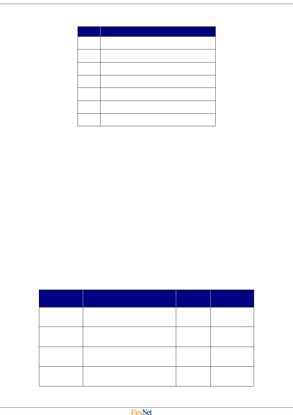
3.1.7 Repeat Level / Status
3.1.8 Application Sequence
An 8 bit modulo 256 counter that increments every time new application data is transmitted by the end
point device.
3.1.9 Application Code
An 8 bit code used to determine the format of the data in the Application Data field.
3.1.10 Application Data
Between 0 and 252 bytes of application data in the future, fixed at 28 for now.
3.1.11 CRC
The 32 bit CCITT Cyclical Redundancy Check sum of all of the bytes from the ID field to the last
Application Data field. Allows for bit error detection and single bit error correction.
3.2 On Air Time Requirements
On air messages take differing amounts of airtime depending on modulation format. The message length of
every message is fixed at 31 bytes. The table below shows the transmission time for each combination:
Bits Repeat Level / Status
0 History Overflow
1In Time Sync
2Tamper
3Brown Out
4 Meter Read Failure
5 RF Sequence Number MSB
6-7 Repeat Level
Modulation Error Correction
Rate
(Hz)
Msg Time
(msec)
Normal Baud Interleaved, Convolutionally
Encoded
8044.5544 107.40
mPass Baud Interleaved, Convolutionally
Encoded
5000.0000 157.60
Boost Baud Interleaved, Convolutionally
Encoded
804.4554 1074.02
Half Baud Interleaved, Convolutionally
Encoded
4022.2772 214.80