
User Manual


Table Of Contents
- Table of Contents
- 1 Introduction
- 2 SmartPoint Module Overview
- 3 On Air Message Format
- 4 On Air Message Types
- 4.1 On Air Message Types
- 4.2 Testing Message – App Code 220
- 4.3 Meter Setup / Configuration Message—App Code 1
- 4.4 Meter Serial Number/Position Binding—App Code 5
- 4.5 GPS Mapping Message
- 4.6 Command Message—App Code 7
- 4.7 Buddy Message—App Code 8
- 4.8 C&I Meter Read With History—App Code 13
- 4.9 C&I Tier Data—App Code 14
- 4.9.1 Message Format
- 4.9.2 Tier Information
- 4.9.3 Meter Type
- 4.9.4 Selected Data Table
- 4.9.5 Data Flags / Peak Demand Time
- 4.9.6 Summation Reading (103 resolution)
- 4.9.7 Demand Reading (100 resolution)
- 4.9.8 Cumulative Demand Reading (103 resolution)
- 4.9.9 Coincident Reading (103 resolution)
- 4.9.10 # Demand Resets
- 4.9.11 Source Indices
- 4.9.12 Quantity of Tier Information
- 4.9.13 Service Quality Message Format
- 4.10 C&I Tunneling Read—App Code 15
- 4.11 C&I Alarm Message – App Code 16
- 4.11.1 Application Data
- 4.11.2 Voltage Phase A,B, and C
- 4.11.3 Click Count
- 4.11.4 Time Since Event
- 4.11.5 Current Meter Reading
- 4.11.6 Extended Time Since Event
- 4.11.7 Device Temperature
- 4.11.8 µP Status
- 4.11.9 Lock Errors
- 4.11.10 Alarm Data
- 4.11.11 Time of Last Power Failure
- 4.11.12 Total # of Outages
- 4.11.13 Flags
- 4.12 Demand History Message—App Code 25
- 4.12.1 Message Format
- 4.12.2 Number of Demand Resets
- 4.12.3 Last Demand Reset Date and Time
- 4.12.4 Last Peak Demand Date and Time
- 4.12.5 Last Peak Demand
- 4.12.6 Last Consumption Reading
- 4.12.7 2nd Demand Reset Date and Time
- 4.12.8 2nd Peak Demand Date and Time
- 4.12.9 2nd Peak Demand
- 4.12.10 2nd Consumption Reading
- 4.13 Load Profile Metadata Message—App Code 28
- 4.14 Load Profile Block Data Message—App Code 29
- 4.15 Firmware Image Check Response—App Code 30
- 4.16 High Res C&I Meter Read with History—App Code 38
- 4.17 Generic Ping Response—App Code 48
- 4.18 C&I High Res Read with History Data—App Code 55
- 4.19 Scratch Pad Image Check Response—App Code 57
- 5 Setup and Configuration
- 5.1 Electrical Configuration Interface
- 5.2 Configurable Parameters
- 5.2.1 End Point ID
- 5.2.2 Meter Sample Rate
- 5.2.3 Supervisory Transmit Rate
- 5.2.4 Base Frequency Channel
- 5.2.5 Transmit Frequency Channels
- 5.2.6 Receive Frequency Channel
- 5.2.7 C&I Mode Channel
- 5.2.8 Priority Mode Channel
- 5.2.9 Transmit Channel Mask
- 5.2.10 Transmit Operational Mode
- 5.2.11 Receiver Operational Mode
- 5.2.12 Enable Encryption
- 5.2.13 Programmer ID
- 5.3 Setup Messages
- 5.4 Status Request (0x91)
- 5.5 Set Device ID (0x92)
- 5.6 Device Static Setup
- 5.7 Set TCXO Correction (0x94)
- 5.8 Set Latitude/Longitude (0x95)
- 5.9 Set A/D Calibration (0x96)
- 5.10 Set Voltage Quality Thresholds (0x97)
- 5.11 Set Encryption Key (0x98)
- 5.12 Set Real Time Clock (0x99)
- 5.13 Send Data (0x9A)
- 5.14 Ping (0x9C)
- 5.15 Set Customer Meter Number (0x9D)
- 5.16 Set Customer ID (0x9E)
- 5.17 Send Data Commands
- 6 Receiver Section
- 6.1 Receiver Requirements
- 6.2 Receiver On Air Command Messages
- 6.2.1 Command Types
- 6.2.2 Command Acknowledge
- 6.2.3 Set Static Setup
- 6.2.4 Set TCXO Correction
- 6.2.5 Set Latitude and Longitude
- 6.2.6 Set VoltVoltage Quality settings:
- 6.2.7 Set
- 6.2.8 On Demand Read / Drive By Read
- 6.2.9 Ping
- 6.2.10 Set Transmitter Id
- 6.2.11 Set Customer Id
- 6.2.12 Set Encryption Key
- 6.2.13 Set Preferred Buddy Id
- 6.2.14 Set Company Meter Number
- 6.2.15 C&I Read C12.19 Data
- 6.2.16 C&I Write C12.19 Data
- 6.2.17 C&I Demand Reset
- 6.3 Command Addressing
- 6.4 Receiver Miscellaneous
- Appendix A FlexNet SmartPoint Radio Overview
- Appendix B Specifications
- Index
SmartPoint Module Overview 2-3
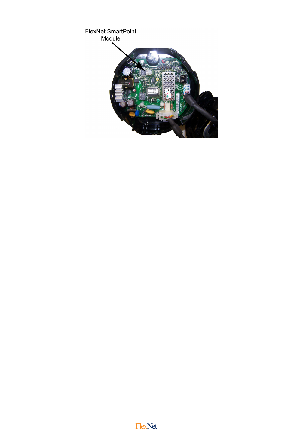
SmartPoint Module for the Elster A3 Meter ECMTM40000
Figure 2-2: Elster Meter with SmartPoint Module Installed
The SmartPoint modules transmit the meter consumption and status information at regular
intervals. Critical meter status and power outage alarms are also monitored on a real-time basis.
The SmartPoint module transmits the meter data to the fixed network using long-range, licensed,
narrowband radio.
The SmartPoint is also able to use mPass Mode, which allows a SmartPoint module to repeat a
data transmission from another SmartPoint device that is blocked from the TGB transceiver, and
allows the TGB transceiver to communicate with a blocked SmartPoint module through another
SmartPoint module.
2.3.2.2 Tower Gateway Base Station
These transmissions are received by one or more TGBs. The TGBs use existing radio towers;
antennas are installed at heights of 200’-650’, providing coverage of 75 to 300 sq. mi. The TGB
includes a Linux computer that communicates to the RNI (see below) via modem. The TGB
forwards the data to the Regional Network Interface (RNI) via phone line, ISDN, Satellite, or WiFi
links, and stores the information locally in the event of RNI communications path interruption. The
transceiver allows for two-way communication over the FlexNet AMI network, allowing commands
to be issued to the SmartPoint modules.
2.3.3 FlexNet AMI Regional Network Interface
The RNI consists of modems and Linux computers with backup power. The RNI controls the TGB sites
and keeps a 60-day log of metering data. It also includes an SQL database that generates reports for
billing and other external system elements. Interfaces are available to a variety of metering databases:
Sensus SiMS, Itron MV-90 and Enterprise Edition. XML and customized interfaces are available.