
User's Manual
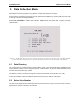
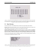
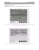

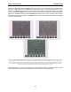
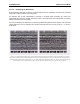
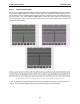
Table Of Contents
- 5 Data Collection Mode
- 6 Surveying Techniques
- 6.1 Low Frequency Reflection (Profiling) Mode
- 6.2 High Frequency Reflection (Profiling) Mode
- 6.3 Antenna Orientation
- 6.4 Triggers
- 6.5 Free Run
- 6.6 Odometer Data Acquisition
- 6.7 Signal Polarity
- 6.8 Spatially Aliasing the Data
- 6.9 Creating a Test Line for Data Quality
- 6.10 Adding GPS for Positioning
- 6.11 Common Mid-Point (CMP) Survey
- 6.12 Transillumination Surveys
- 7 Troubleshooting
- 8 File Management
- 9 Care and Maintenance
- 10 Helpful Hints
- Appendix A: Data File Formats
- Appendix B: GPR Signal Processing Artifacts
- Appendix C: Excerpts from the HP Fiber Optic Handbook
- Appendix D: Health & Safety Certification
- Appendix E: FCC Regulations
- Appendix F: Instrument Interference
- Appendix G: Safety Around Explosive Devices

pulseEKKO PRO 5-Data Collection Mode
71
Error Messages: Messages will be displayed if any system connection is incorrect or if there is a problem
with the system (Section 7: P95).
Collect Screen: A sample of a screen data plot while in COLLECT mode is shown in Figure 5-4.
Figure 5-4: Data collection screen with traces plotted in grey scale. The horizontal distance of data plotted on the screen depends
on the pixel width of the traces (Section 3.5.1: P56)
Figure 5-5: Data collection screen with traces plotted in wiggle trace mode with shading on the right (Section 3.5.1: P56)