
User's Manual
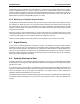
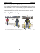
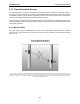
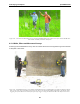
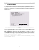
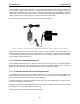
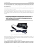
Table Of Contents
- 5 Data Collection Mode
- 6 Surveying Techniques
- 6.1 Low Frequency Reflection (Profiling) Mode
- 6.2 High Frequency Reflection (Profiling) Mode
- 6.3 Antenna Orientation
- 6.4 Triggers
- 6.5 Free Run
- 6.6 Odometer Data Acquisition
- 6.7 Signal Polarity
- 6.8 Spatially Aliasing the Data
- 6.9 Creating a Test Line for Data Quality
- 6.10 Adding GPS for Positioning
- 6.11 Common Mid-Point (CMP) Survey
- 6.12 Transillumination Surveys
- 7 Troubleshooting
- 8 File Management
- 9 Care and Maintenance
- 10 Helpful Hints
- Appendix A: Data File Formats
- Appendix B: GPR Signal Processing Artifacts
- Appendix C: Excerpts from the HP Fiber Optic Handbook
- Appendix D: Health & Safety Certification
- Appendix E: FCC Regulations
- Appendix F: Instrument Interference
- Appendix G: Safety Around Explosive Devices

6-Surveying Techniques pulseEKKO PRO
94
Figure 6-13: Cross hole transillumination surveys with the pulseEKKO PRO system require the use of 50, 100 or 200 MHz bore-
hole antennas available from Sensors & Software.
6.12.2 Walls, Pillars and Monument Surveys
Another type of transillumination survey uses the surface antennas to send signals through a structure like
a wall, pillar or monument.
Figure 6-14: Transillumination survey setup. With a transillumination survey, the GPR signal is sent from the transmitter directly
to the receiver after it has passed through a structure. The DVL is centrally located and data acquisition is controlled by either
triggering the system with the electrical or fibre optic beeper/trigger or using Free Run mode with a time delay between traces.