
User's Manual
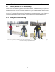
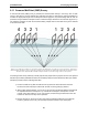
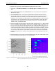
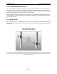
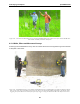
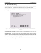
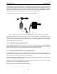
Table Of Contents
- 5 Data Collection Mode
- 6 Surveying Techniques
- 6.1 Low Frequency Reflection (Profiling) Mode
- 6.2 High Frequency Reflection (Profiling) Mode
- 6.3 Antenna Orientation
- 6.4 Triggers
- 6.5 Free Run
- 6.6 Odometer Data Acquisition
- 6.7 Signal Polarity
- 6.8 Spatially Aliasing the Data
- 6.9 Creating a Test Line for Data Quality
- 6.10 Adding GPS for Positioning
- 6.11 Common Mid-Point (CMP) Survey
- 6.12 Transillumination Surveys
- 7 Troubleshooting
- 8 File Management
- 9 Care and Maintenance
- 10 Helpful Hints
- Appendix A: Data File Formats
- Appendix B: GPR Signal Processing Artifacts
- Appendix C: Excerpts from the HP Fiber Optic Handbook
- Appendix D: Health & Safety Certification
- Appendix E: FCC Regulations
- Appendix F: Instrument Interference
- Appendix G: Safety Around Explosive Devices

pulseEKKO PRO 6-Surveying Techniques
89
If maintaining speed is important, the other option is to reduce the time window (Section 3.2.2: P35) or
number of stacks (Section 3.2.7: P40) to allow the traces to be collected faster. Data trace acquisition
speed can also be increased by increasing the temporal sampling interval but it is important to make sure
that the temporal sampling interval does not exceed twice the recommended value or the data will be
aliased and may become uninterpretable (Section 3.2.3: P36).
6.6.2 Backing up to Pinpoint Target Positions
The Big Wheel and SmartCart odometers allow the user to stop the GPR system in the middle of a survey
line and back up. When this is done, an arrow and vertical line appear on the data image and move back
along the image as the system moves backwards. This makes it possible to correlate a target in the data
image to an exact location on the ground. Once the arrow lines up with the target, mark the ground at the
mid point of the antennas.
When the system is moved forward again to continue with the survey, the GPR system does not start
collecting data again until you reach the position where you stopped at. This feature is useful for producing
a continuous data image even if the system is backed up during the survey line.
Note that it is not possible to back up and have the arrow indicator move more than one screen.
6.7 Signal Polarity
In the course of collecting data along a profile line or lines, it is important to keep the relative antenna
orientation the same (note: it is the electronic unit orientation which controls the polarity, antenna direction
alone does not affect polarity), especially after any interruption in data collection to change batteries, etc.
One way to control polarity is to always have the pulseEKKO name pointed in the direction of antenna
movement. If this precaution is not followed, the signals may have reverse polarity (this can be corrected in
EKKO_View Deluxe program if necessary).
6.8 Spatially Aliasing the Data
Increasing production by increasing the step size is not always a good idea. Undersampling the data with
a step size that is too large can make interpretation difficult. Use the guidelines to set step size properly
(Section 3.2.5: P38).
If you are surveying for a large target, it is possible to increase the step size to maximize productivity and
minimize the data volume but keep in mind that the step size should still be small enough that one or more
traces are collected over top of the target. For example, if your target is 0.3m (1 foot) in diameter the
maximum step size should be about 0.1m (0.33 feet).
If the objective of the survey is to follow a flat-lying layer like a soil layer or asphalt that varies little laterally,
the step size could be increased to 1.0m or more. As a rule of thumb its better to collect more data than not
enough.