
User's Manual
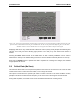
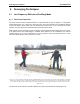
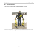
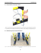

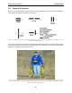
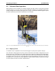
Table Of Contents
- 5 Data Collection Mode
- 6 Surveying Techniques
- 6.1 Low Frequency Reflection (Profiling) Mode
- 6.2 High Frequency Reflection (Profiling) Mode
- 6.3 Antenna Orientation
- 6.4 Triggers
- 6.5 Free Run
- 6.6 Odometer Data Acquisition
- 6.7 Signal Polarity
- 6.8 Spatially Aliasing the Data
- 6.9 Creating a Test Line for Data Quality
- 6.10 Adding GPS for Positioning
- 6.11 Common Mid-Point (CMP) Survey
- 6.12 Transillumination Surveys
- 7 Troubleshooting
- 8 File Management
- 9 Care and Maintenance
- 10 Helpful Hints
- Appendix A: Data File Formats
- Appendix B: GPR Signal Processing Artifacts
- Appendix C: Excerpts from the HP Fiber Optic Handbook
- Appendix D: Health & Safety Certification
- Appendix E: FCC Regulations
- Appendix F: Instrument Interference
- Appendix G: Safety Around Explosive Devices

6-Surveying Techniques pulseEKKO PRO
86
6.3 Antenna Orientation
Both the high and low frequency, bistatic antennas of the pulseEKKO PRO system have the flexibility to
allow different orientations with respect to one another.
Figure 6-6: Definitions of antenna orientations available with bistatic antennas. Perpendicular-Broadside (PR-BD) is most com-
monly used for reflection surveys.
The most common antenna orientation is the parallel-broadside configuration. This orientation provides the
best coupling between antennas and the most energy in the direction of the survey line which reduces
reflections from targets off to the side of the line.
Figure 6-7: Most common reflection surveying technique. Antennas are held at the proper antenna separation for the selected fre-
quency and perpendicular to the survey line direction. This antenna orientation ensures the maximum in-line GPR energy and
reduces reflections from off-line targets.