
User's Manual


2-System Assembly and Startup pulseEKKO PRO
4
2.2 DVL and Control Module
The DVL and Control Module are common to all configurations.
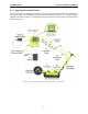
2.2.1 Attaching the Control Module to the DVL
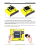
The control module unit must be attached to the back of the DVL (Figure 2-3). This may already have been
done at the factory. Proceed to the next section, if this is the case.
Figure 2-3: The DVL with the control module attached to the back.
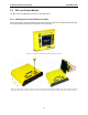
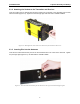
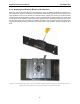
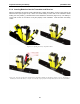
Figure 2-4: Remove the 4 yellow caps and the 4 screws from the back of the DVL (left) and place the control module on the back
of the DVL (right). Make sure that the 37 pin connector is aligned properly with the 37 socket connector on the control module.