
User's Manual
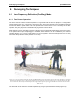
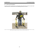
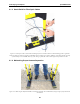
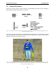
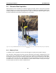
Table Of Contents
- 5 Data Collection Mode
- 6 Surveying Techniques
- 6.1 Low Frequency Reflection (Profiling) Mode
- 6.2 High Frequency Reflection (Profiling) Mode
- 6.3 Antenna Orientation
- 6.4 Triggers
- 6.5 Free Run
- 6.6 Odometer Data Acquisition
- 6.7 Signal Polarity
- 6.8 Spatially Aliasing the Data
- 6.9 Creating a Test Line for Data Quality
- 6.10 Adding GPS for Positioning
- 6.11 Common Mid-Point (CMP) Survey
- 6.12 Transillumination Surveys
- 7 Troubleshooting
- 8 File Management
- 9 Care and Maintenance
- 10 Helpful Hints
- Appendix A: Data File Formats
- Appendix B: GPR Signal Processing Artifacts
- Appendix C: Excerpts from the HP Fiber Optic Handbook
- Appendix D: Health & Safety Certification
- Appendix E: FCC Regulations
- Appendix F: Instrument Interference
- Appendix G: Safety Around Explosive Devices

6-Surveying Techniques pulseEKKO PRO
82
6 Surveying Techniques
6.1 Low Frequency Reflection (Profiling) Mode
6.1.1 Two Person Operation
The most common method of data acquisition in rough terrain will be with two people in a configuration
shown below (Figure 6-1). The person carrying the DVL and Control module has a belt battery fastened
around their waist to power these units. The optional DVL carrier shown is not a necessity for the DVL
operator. They may be just as comfortable carrying the DVL in their hands.
Data collection can be controlled by the DVL operator using the electrical beeper/trigger or the DVL button.
If the optional fibre optic beeper/trigger is available, data collection can be controlled by the antenna
operator (Section 3.3.1.1: P43). A third option is to run the system in free Run mode (Section 3.3.1.3: P43)
with a time delay between traces (Section 3.3.3: P44).
Figure 6-1: Two person data collection with the pulseEKKO PRO system. The antenna operator moves the antennas to each data
location point. The data trace is collected by the DVL operator using the electrical beeper/trigger or the DVL button. The data
trace can also be collected by the antenna operator using the fibre optic beeper/trigger. The data are visible in real time on the
DVL screen.
The antennas can be held at a constant separation by using a rope tied between them (Figure 6-4).