
User's Manual


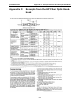

Table Of Contents
- 5 Data Collection Mode
- 6 Surveying Techniques
- 6.1 Low Frequency Reflection (Profiling) Mode
- 6.2 High Frequency Reflection (Profiling) Mode
- 6.3 Antenna Orientation
- 6.4 Triggers
- 6.5 Free Run
- 6.6 Odometer Data Acquisition
- 6.7 Signal Polarity
- 6.8 Spatially Aliasing the Data
- 6.9 Creating a Test Line for Data Quality
- 6.10 Adding GPS for Positioning
- 6.11 Common Mid-Point (CMP) Survey
- 6.12 Transillumination Surveys
- 7 Troubleshooting
- 8 File Management
- 9 Care and Maintenance
- 10 Helpful Hints
- Appendix A: Data File Formats
- Appendix B: GPR Signal Processing Artifacts
- Appendix C: Excerpts from the HP Fiber Optic Handbook
- Appendix D: Health & Safety Certification
- Appendix E: FCC Regulations
- Appendix F: Instrument Interference
- Appendix G: Safety Around Explosive Devices

pulseEKKO PRO Appendix A: Data File Formats
A-1
Appendix A: Data File Formats
pulseEKKO Data File Format
HEADER (.HD) FILE:
The header file, identified by the file extension .HD, is an ASCII file. An example is shown below.
1234
Data Collected with pulseEKKO PRO
2005-01-12
NUMBER OF TRACES = 136
NUMBER OF PTS/TRC = 409
TIMEZERO AT POINT = 96
TOTAL TIME WINDOW = 327
STARTING POSITION = 9.500000
FINAL POSITION = 77.000000
STEP SIZE USED = 0.500000
POSITION UNITS = metres
NOMINAL FREQUENCY = 100.000000
ANTENNA SEPARATION = 1.000000
PULSER VOLTAGE (V) = 400
NUMBER OF STACKS = 128
SURVEY MODE = Reflection
DVL Serial# = 0000-0000-3333
Console Serial# = 0022-3009-0024
Transmitter Serial# = 0026-3171-0005
Receiver Serial# = 0025-3172-0004
It can be read and/or printed using any Word Processor.
DATA (.DT1) FILE:
The data file contains as many records as there are traces. Each record in turn consists of a header sec-
tion and a data section. The header section consists of an array of 25 real*4 numbers and a string of 28
characters which is used for annotation. The 25 element real array contains the following information:
Item # Description
1 Trace number
2 Position
3 Number of points per trace
4 Topographic data, if available
5 (not used)
6 # bytes/point (always 2 for Rev 3 firmware)
7 Time Window
8 # of stacks
9 Time window
9-10 reserved for GPS X position (double*8 number)
11-12 reserved for GPS Y position (double*8 number)
13-14 reserved for GPS Z position (double*8 number)
15 reserved for receiver x position
16 reserved for receiver y position
17 reserved for receiver z position
18 reserved for transmitter x position
19 reserved for transmitter y position
20 reserved for transmitter z position
21 timezero adjustment
where:point(x)= point(x+adjustment)