
User's Manual
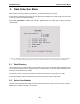
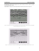
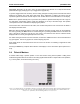
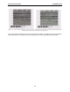
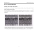
Table Of Contents
- 5 Data Collection Mode
- 6 Surveying Techniques
- 6.1 Low Frequency Reflection (Profiling) Mode
- 6.2 High Frequency Reflection (Profiling) Mode
- 6.3 Antenna Orientation
- 6.4 Triggers
- 6.5 Free Run
- 6.6 Odometer Data Acquisition
- 6.7 Signal Polarity
- 6.8 Spatially Aliasing the Data
- 6.9 Creating a Test Line for Data Quality
- 6.10 Adding GPS for Positioning
- 6.11 Common Mid-Point (CMP) Survey
- 6.12 Transillumination Surveys
- 7 Troubleshooting
- 8 File Management
- 9 Care and Maintenance
- 10 Helpful Hints
- Appendix A: Data File Formats
- Appendix B: GPR Signal Processing Artifacts
- Appendix C: Excerpts from the HP Fiber Optic Handbook
- Appendix D: Health & Safety Certification
- Appendix E: FCC Regulations
- Appendix F: Instrument Interference
- Appendix G: Safety Around Explosive Devices

pulseEKKO PRO 5-Data Collection Mode
73
A fiducial marker is activated by pressing the Fiducial button or the A button on the keypad during data
acquisition (see Figure 5-4).
The position and name of the object encountered at each marker can be recorded in a field notebook.
The fiducial marker is written to the trace header of the next trace to be collected. Fiducial markers are
numbered sequentially (F1, F2 etc.). When the data are transferred to a PC and reviewed, these markers
can assist with data interpretation.
5.4.1 Fiducial Markers for Rubberbanding
Fiducial markers are useful when the data line is to be “rubberbanded”. If fiducial markers corresponding to
known positions are added to the data during data acquisition, these known positions can be used to
stretch or squeeze the data line to a constant step size. This makes it possible to estimate the required
step size and collect data without a tape measure or other measuring device, as long as there are a few
locations along the survey line where the position is known.
The rubberbanding routine is a post-processing step available in the EKKO_View Enhanced and
EKKO_View Deluxe software packages.
5.4.2 Fiducial Markers for GPS
If a GPS receiver is attached to the DVL, a file containing GPS information can be saved (Section 3.3.4:
P44). In “On a Tag” mode, a line of GPS information will be added to the GPS file (Section 3.3.4.1: P45)
whenever a fiducial marker is added to the data.
5.5 Data Collection Pause Menu
Pressing the Pause button suspends the data collection cycle and displays a menu that is displayed at the
bottom of the screen. The menu items are:
5.5.1 Exit
Exit from the data acquisition of the current line and go back to the Line Number screen (See Figure 5-2 on
page 70) to prepare for the collection of the next line.
5.5.2 Continue
Go back to Collect mode and continue with the data collection of the current line.
5.5.3 Scale
During data acquisition, the time axis is not plotted on the image. To view the time axis, pause the data
collection and select Scale. When Scale is pressed once a time axis will appear on the left of the data
image (Figure 5-7, left). If Scale is pressed a second time, a depth axis will appear on the left of the data
image (Figure 5-7, right).