
User's Manual

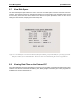
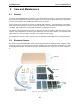
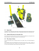
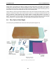
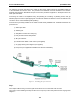


Table Of Contents
- 5 Data Collection Mode
- 6 Surveying Techniques
- 6.1 Low Frequency Reflection (Profiling) Mode
- 6.2 High Frequency Reflection (Profiling) Mode
- 6.3 Antenna Orientation
- 6.4 Triggers
- 6.5 Free Run
- 6.6 Odometer Data Acquisition
- 6.7 Signal Polarity
- 6.8 Spatially Aliasing the Data
- 6.9 Creating a Test Line for Data Quality
- 6.10 Adding GPS for Positioning
- 6.11 Common Mid-Point (CMP) Survey
- 6.12 Transillumination Surveys
- 7 Troubleshooting
- 8 File Management
- 9 Care and Maintenance
- 10 Helpful Hints
- Appendix A: Data File Formats
- Appendix B: GPR Signal Processing Artifacts
- Appendix C: Excerpts from the HP Fiber Optic Handbook
- Appendix D: Health & Safety Certification
- Appendix E: FCC Regulations
- Appendix F: Instrument Interference
- Appendix G: Safety Around Explosive Devices

pulseEKKO PRO 9-Care and Maintenance
115
Step 2
Slide the two strain relief jackets over the fibres remembering that the blue fibre optic connector will
correspond with the black strain relief jacket and the grey fibre optic connector with the grey strain relief
jacket.
Step 3
Place the crimp ring and the connector over the end of the cable; the fibre should protrude about 0.12 inch
(3 mm) through the end of the connector. Carefully position the ring so that it is entirely on the connector
and then crimp the ring in place with the crimping tool.
NOTE: Place the grey connector on the cable end to be connected to the fibre optic output
(grey strain relief jacket) and the blue connector on the cable end to be connected to the
fibre optic input (black strain relief jacket) to maintain the color coding (both connectors
are the same mechanically).
Step 4
Slide one of the plastic washers provided in your pulseEKKO PRO spares kit over the fibre optic connector.
This washer will now be inserted into the strain relief jacket.
NOTE: You may also use #8 stainless steel flat washers should you run out of the nylon
ones. Being very careful not to damage or bend the cable, force the washer into the strain
relief jacket. You may find it useful to use a 3/16 inch nut driver to push the washer into
its strain relief jacket as the fibre optic connector will slide inside the driver and even
force can be applied to the washer.
Step 5
Any excess fibre protruding from the connector may be cut off; however the trimmed fibre should protrude
at least 0.04 inch (1 mm) from the connector end.
Insert the connector fully into the polishing fixture and the connector end protruding from the bottom of the
fixture.
NOTE: The four dots on the bottom of the fixture are wear indicators. Replace the fixture
when the dots are no longer visible.
Place the 600 grit abrasive paper on a flat smooth surface. Pressing down on the connector, polish the
fibre and the connector until the connector is flush with the end of the polishing fixture. Wipe the connector
and the fixture with a clean cloth or tissue.