
User's Manual
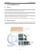
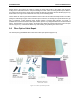
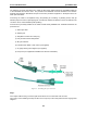


Table Of Contents
- 5 Data Collection Mode
- 6 Surveying Techniques
- 6.1 Low Frequency Reflection (Profiling) Mode
- 6.2 High Frequency Reflection (Profiling) Mode
- 6.3 Antenna Orientation
- 6.4 Triggers
- 6.5 Free Run
- 6.6 Odometer Data Acquisition
- 6.7 Signal Polarity
- 6.8 Spatially Aliasing the Data
- 6.9 Creating a Test Line for Data Quality
- 6.10 Adding GPS for Positioning
- 6.11 Common Mid-Point (CMP) Survey
- 6.12 Transillumination Surveys
- 7 Troubleshooting
- 8 File Management
- 9 Care and Maintenance
- 10 Helpful Hints
- Appendix A: Data File Formats
- Appendix B: GPR Signal Processing Artifacts
- Appendix C: Excerpts from the HP Fiber Optic Handbook
- Appendix D: Health & Safety Certification
- Appendix E: FCC Regulations
- Appendix F: Instrument Interference
- Appendix G: Safety Around Explosive Devices

9-Care and Maintenance pulseEKKO PRO
114
The following procedure describes how to repair the fibre optics cables that link the pulseEKKO PRO unit
to the transmitter and receiver units. The procedure and materials used are described in the Hewlett-
Packard Opto-Electronic Data Book excerpts of which are provided in Appendix C: Excerpts from the HP
Fiber Optic Handbook.
Connecting the cable is accomplished using the polishing kit consisting of polishing fixture, 600 grit
abrasive paper and 3 micron pink lapping film. No adhesive material is needed to secure the cable and the
connector can be used immediately after polishing.
Connectors may be easily installed on the cable end with readily available tools. Materials needed for the
procedure are:
1) Fibre optic cable
2) Polishing Kit
3) Grey/Blue connector and crimp ring
4) Grey and black strain relief jackets
5) #8 nylon washers
6) Industrial razor blade or wire cutters (not supplied)
7) 16 gauge latching wire strippers (not supplied)
8) Crimp tool (not supplied but available from Sensors & Software)
Figure 9-4: Assembling fibre optic connectors.
Step 1
If the duplex cable is being connected, split the two fibres 2 to 3 inches back from the ends.
Trim off any excess webbing and strip off about 0.3 inch (8 mm) of the outer jacket with the 16 gauge wire
strippers.