
User's Manual
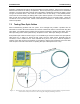
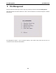
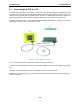
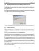
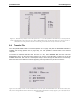
Table Of Contents
- 5 Data Collection Mode
- 6 Surveying Techniques
- 6.1 Low Frequency Reflection (Profiling) Mode
- 6.2 High Frequency Reflection (Profiling) Mode
- 6.3 Antenna Orientation
- 6.4 Triggers
- 6.5 Free Run
- 6.6 Odometer Data Acquisition
- 6.7 Signal Polarity
- 6.8 Spatially Aliasing the Data
- 6.9 Creating a Test Line for Data Quality
- 6.10 Adding GPS for Positioning
- 6.11 Common Mid-Point (CMP) Survey
- 6.12 Transillumination Surveys
- 7 Troubleshooting
- 8 File Management
- 9 Care and Maintenance
- 10 Helpful Hints
- Appendix A: Data File Formats
- Appendix B: GPR Signal Processing Artifacts
- Appendix C: Excerpts from the HP Fiber Optic Handbook
- Appendix D: Health & Safety Certification
- Appendix E: FCC Regulations
- Appendix F: Instrument Interference
- Appendix G: Safety Around Explosive Devices

pulseEKKO PRO 8-File Management
105
8.1 Connecting the DVL to a PC
To transfer all the data files in one directory from the DVL to an external computer, the computer must be
connected to the DVL using the special parallel PXFER cable that is supplied with the system (Figure 8-1).
Note that this is a special cable and standard 25 pin to 25 pin or Laplink cables will not work. As well, the
computer must have the utility program called WinPXFER running on it (Section 8.2 on page 106).
To transfer data from a DVL a cable called the parallel XFER (PXFER) cable is required. This cable is
designed to connect the DVL to an external computer.
Figure 8-1: Parallel PXFER cable connections
The 2 connections that must be made before attempting to transfer data are:
1) Attach the 25 socket parallel connector to the 25 socket parallel port on back of the Digital Video Logger,
and
2) Attach the 25 socket parallel connector the parallel port of the external computer.
WARNING: To avoid damaging any of the components, turn off the DVL and computer before making any
of these connections.