Users Manual Version 1.
Smart Systems User’s Manual Version 1.
Smart Systems User’s Manual Version 1.1 Information on pulseEKKO, Noggin and Conquest Products Regarding Electromagnetic Emissions Emissions All governments have regulations on the level of electromagnetic emissions that an electronic apparatus can emit. The objective is to assure that one apparatus or device does not interfere with any other apparatus or device in such a way as to make the other apparatus non-functional. Sensors & Software Inc.
Smart Systems User’s Manual Version 1.1 Sensors & Software Inc. monitors the research in this area. To date, the power levels of Sensors & Software Inc.’s products are so small as to be inconsequential compared to other common sources. If you are happy that a cell phone is not hazardous, then Sensors & Software Inc.’s product, being of much lower power, need be of little concern. Also see Appendix B - Health & Safety Certification.
Smart Systems User’s Manual Version 1.1 Copyright and Warranty Information Software Licence & Limited Warranty Important: Please read this document carefully before removing the SOFTWARE PRODUCT diskettes from their protective cover or assembling the HARDWARE PRODUCT . By removing the diskettes or assembling the hardware, you are agreeing to become bound by the terms of this agreement. If you do not agree to the terms of this agreement, promptly contact Sensors & Software, Inc.
Smart Systems User’s Manual Version 1.1 Product Limited Warranty SSI warrants the HARDWAR E PRODUCT to be free from defect in material and workmanship under normal use for a period of ninety (90) days from the date of shipment. Any computer systems purchased with the product are subject to the manufacturer's warranty and not the responsibility of SSI.
Smart Systems User’s Manual Version 1.1 Serviceability Should any term of this agreement be declared void or not enforceable by any court of competent jurisdiction, the remaining terms shall remain in full effect.
Smart Systems User’s Manual Version 1.
Smart Systems User’s Manual Version 1.1 TABLE OF CONTENTS 1 GENERAL OVERVIEW...........................................................................................1 2 ASSEMBLING THE SMART CART......................................................................2 2.1 3 3.1 Configuring the Smart Cart to Carry a Different Noggin System..................................................10 ASSEMBLING THE SMART HANDLE SYSTEM.............................................11 Smart Handle .................
Smart Systems User’s Manual Version 1.1 Input a Velocity Value ........................................................................................................................................ 30 5.3.5 Depth Menu................................................................................................................................................. 31 5.3.6 Gain Menu.................................................................................................................................
Smart Systems User’s Manual Version 1.1 5.8 Advanced Topics ...........................................................................................................................................54 5.8.1 How Depth is Determined ........................................................................................................................ 54 6 NOGGIN PLUS ............................................................................................................55 6.
Smart Systems User’s Manual Version 1.1 X Lines Only - Forward ................................................................................................................................. 75 Y Lines Only - Forward ................................................................................................................................. 76 XY Lines - Forward ........................................................................................................................................
Smart Systems User’s Manual Version 1.1 8.3 Skid Pads .........................................................................................................................................................95 APPENDIX A NOGGIN PLUS DATA FILE FORMAT.............................................A-1 APPENDIX B HEALTH AND SAFETY CERTIFICATION .................................B-1 APPENDIX C FCC REGULATIONS......................................................................
Smart Systems User’s Manual Version 1.
Smart Systems User’s Manual Version 1.1 1 General Overview Noggin Smart Systems are integrated ground penetrating radar (GPR) data acquisition platforms. Once the unit has been assembled and powered up you can be carrying out a GPR survey in less than a minute. There are two different configurations available, the Smart Cart system and the Smart Handle system (see Figure 1-1). The Smart Cart system consists of the cart structure, a Noggin, an odometer wheel, a digital video logger (DVL), and a battery.
Smart Systems User’s Manual Version 1.1 2 Assembling the Smart Cart The Noggin Smart Cart can be configured for Noggin 250, Noggin 500 or Noggin 1000 operation. For the Noggin 250 Smart Cart, refer to Figure 2-10. For the Noggin 500 Smart Cart, refer to Figure 2-11 and for the Noggin 1000 Smart Cart, refer to Figure 2-12.
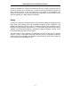
Smart Systems User’s Manual Version 1.1 The Noggin Smart Cart comes fully assembled but in collapsed position (Figure 2-2). The steps necessary to have a fully functioning system are: Figure 2-2: Smart Cart in collapsed position. 1. Attach wheels (if necessary): The Smart Cart may have been shipped without the wheels attached or they may have been removed for storage.
Smart Systems User’s Manual Version 1.1 a ¼ inch Allen (hexagonal) wrench to loosen the screws on the side of the odometer (see Figure 2-10 or Figure 2-11) and pivot the entire odometer unit until the small odometer wheel makes good contact with the side of the cart wheel. Then tighten the screws to lock the odometer wheel in this position. After this has been done, it will be necessary to re-calibrate the odometer (see Section 6.5.2). Figure 2-4: Smart Cart set up. 3.
Smart Systems User’s Manual Version 1.1 Once all 4 swivel adapters are attached, the Noggin can then be attached to the Smart Cart. The Noggin is usually attached to the cart with the long axis of the Noggin unit parallel to the wheels on the cart (see Figure 2-10 ,Figure 2-11 and Figure 2-12). For this orientation, make sure the 37 socket female electrical receptacle on the Noggin faces the back of the cart so that the cable on the cart will reach the receptacle.
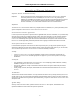
Smart Systems User’s Manual Version 1.1 Attach Cross bars to the cart (if necessary). a) Line up holes. b) Insert Clevis pin. Attach Noggin to cross bar. a) Insert cross bar into swivel adapter. b) Insert Clevis pin. Figure 2-7: Attaching the Noggin 500 and Noggin 1000 to the cart. Connect the cable with the 37-pin male D connector to the Noggin and secure this attachment by tightening the hand screws. 4.
Smart Systems User’s Manual Version 1.1 Figure 2-8: Attaching the digital video logger (DVL). Step 1: Depress flexible clip. Step 2: Slide DVL onto shelf. Once the Digital Video Logger is in place, attach the cable with the 37-socket female Dconnector to the 37-pin receptacle on the back of the Digital Video Logger. This attachment can be secured by tightening the hand screws. The Digital Video Logger can be pivoted to adjust the view angle.
Smart Systems User’s Manual Version 1.1 5. Attach the Battery Unit: Set the battery unit onto the lower inclined shelf on the back of the Smart Cart (see Figure 2-9). The handle on the battery unit should be accessible from the back of the cart with the cable receptacle on the right. The battery unit should rest in this area without moving. To secure the battery onto the cart, put the straps provided over the battery unit and lock into place with the plastic buckle. Tighten the straps if necessary.
Smart Systems User’s Manual Version 1.
Smart Systems User’s Manual Version 1.1 2.1 Configuring the Smart Cart to Carry a Different Noggin System The Noggin Smart Cart can be configured to carry a Noggin 250, Noggin 500 or a Noggin 1000 system. This can be done by replacing the two support arms on the cart (see Figure 2-13) with the support arms for another system. Each arm is attached to the cart by two hand screws. For each arm, remove the screws, detach the arm from the cart and replace it with the new arm.
Smart Systems User’s Manual Version 1.
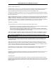
Smart Systems User’s Manual Version 1.1 3.1 Smart Handle The Smart Handle consists of the Smart Handle grip and Smart Handle extension. These two pieces are put together (see Figure 3-2 and Figure 3-3) and then attached to the Noggin (see Figure 3-4). The system can be deployed without the handle extension as shown in Figure 3-5 and Figure 3-6.
Smart Systems User’s Manual Version 1.1 Figure 3-4: Now connect the other end of the Smart Handle extension to the Noggin by simply pushing it in. Figure 3-5: For wall and ceiling scans in tunnels, it may be easier to just connect the Smart Handle grip to the Noggin without the extension. Figure 3-6: To separate either the short or long handle from the Noggin, press on the large grey button on the pole extending from the Noggin and pull apart.
Smart Systems User’s Manual Version 1.1 3.2 Cabling 3.2.1 DVL to Sensor Cable The DVL to Noggin cable is a Y-shaped cable with 3 connections; one to the Noggin sensor, one to the DVL and one to the power supply (battery or AC). Noggin Connection: The first connection is to attach the 37-pin connector on the cable to the 37-socket connector on the Noggin. Use the thumb screws to secure this connection. From the Noggin, the DVL to Sensor Cable runs up the side of the Smart Handle.
Smart Systems User’s Manual Version 1.1 Power Connection: The third connection on the Smart Handle cable attaches to a power supply. The round, 4-pin connector attaches to either the standard battery or optional AC adapter. 3.2.2 Odometer Cable The cable connecting the odometer or positioning wheel comes already installed at the factory. 3.2.3 Smart Grip Cable The Smart Grip Cable is used to connect the Smart Handle button and beeper into the system.
Smart Systems User’s Manual Version 1.1 4 Starting the Digital Video Logger Once all the cable connections are made between the Noggin, the Digital Video Logger (DVL) and the battery, the upper red LED light on the DVL panel should be lit. If the battery voltage is low, the light will flash for about 30 seconds and go out. If the light flashes or does not appear, check the connections and make sure the battery is fully charged. (See Section 8.1 for more information on battery care.
Smart Systems User’s Manual Version 1.1 Screen: The DVL screen is a grayscale LCD selected for its wide temperature range and visibility in sunlight. Visibility can be a major problem with viewing GPR data displays outdoors and considerable effort has been expended on getting a readily visible outdoor display. Brightness: The yellow Brightness control arrows are used to increase and decrease the screen brightness.
Smart Systems User’s Manual Version 1.1 When the Smart Cart is not being used, do not leave the battery plugged in. The system draws about 0.1 amps even when it is powered off and this will gradually drain the battery. 4.1 Running a DVL Detached from a Smart System When collecting data with a Smart System, the DVL is powered by the system battery.
Smart Systems User’s Manual Version 1.1 5 Noggin 5.1 Overview of Noggin Menu Options The Noggin main menu has the following choices: A – RUN B – DEMO 1 – NOGGIN SETUP 2 – TRANSFER ALL BUFFERS 3 – DELETE ALL BUFFERS 4 – UPGRADES 7 – RETURN 12.1 V Rev 6.00 5.1.1 Run Pressing the A button starts the Noggin data acquisition program (see Section 5.4). 5.1.2 Demo Pressing the B button starts the Noggin Demonstration program.
Smart Systems User’s Manual Version 1.1 5.1.5 Delete All Buffers Pressing the number 3 on the main menu allows the us er to delete ALL the data buffers currently saved on the DVL. See Section 5.6.2 5.1.6 Upgrades Pressing the number 4 on the main menu puts the DVL into listen mode to allow a software upgrade to be transferred from an external PC to the DVL. Avoid pressing this button until the instructions in a software upgrade tell you to.
Smart Systems User’s Manual Version 1.1 5.2 Noggin Screen Overview The Noggin screen is shown in Figure 5-1. It is divided into 3 sections. The very top section (Section A) contains velocity, total depth and positioning information. The center section (Section B) contains the actual data and the bottom section (Section C) contains the menu. Each screen of data is saved in the Digital Video Logger as an individual PCX graphics file called a SPI file.
Smart Systems User’s Manual Version 1.1 5.2.1 Section A - Data Parameters Section A displays three items: 1) 2) 3) The total depth to the bottom of the data image in Section B, The velocity used to calculate the total depth and the depth lines (see Depth Lines in Section 5.2.2) and The position indicator in meters or feet (depending on the odometer units set, see Section 5.5.1 – Units).
Smart Systems User’s Manual Version 1.1 Start of Section Indicator Any time the Start button is pressed, the current date and time are written vertically on the screen to indicate the start of a new section (see Section 5.5.1 on how to set time and date on the DVL). The position indicator is also reset to zero. The current date and time can be recorded in a field notebook along with the survey location to help the user organize where each section of data was collected (Figure 5-2).
Smart Systems User’s Manual Version 1.1 5.2.3 Section C - Menu The bottom section contains the user menu selection and current program settings. This menu is described in more detail in Section 5.3. During data acquisition it also displays the current odometer position and the Repeat Trace Number that indicates if the system is moving too quickly and reducing data quality (see Section 5.4.1). 5.3 Noggin Menu Options The default menu selection is divided up into 7 sections: Exit, Print, View, Calib.
Smart Systems User’s Manual Version 1.1 Canon BubbleJet printers can usually be configured to emulate an Epson and most HP printers will work using the Laser driver. Figure 5-3: Attaching a printer to the DVL using a standard printer cable. On the back of the DVL there is a standard 25 socket parallel port. A printer can be attached to the parallel port on the DVL with a standard printer cable, just as you would attach a printer to any computer (Figure 5-3).
Smart Systems User’s Manual Version 1.1 The right edge of the plot must now be defined the same as the left, however now using the right edge of the Digital Video Logger screen. Note that the right edge cannot exceed the left edge. Next, select the type of printer attached (LASER for HP LaserJets and many other HP printers, EPSON for Epson or Canon BubbleJet printers or SEIKO for the Seiko DPU5400 Thermal printer).