
User's Manual
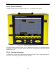
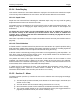
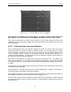
Table Of Contents
- 1 General Overview
- 2 Noggin Components
- 3 Noggin 100 Assembly
- 4 SmartCart Assembly
- 5 SmartTow Assembly
- 6 SmartHandle Assembly (Noggin 500 & 1000 only)
- 7 Rock Noggin Assembly (Noggin 500 & 1000 only)
- 8 Connecting GPS
- 9 Digital Video Logger (DVL)
- 10 Powering Up the System
- 11 Locate & Mark Mode
- 12 Survey & Map Mode
- 12.1 Survey & Map Menu
- 12.2 Data Acquisition
- 12.2.1 Replaying or Overwriting Data
- 12.2.2 Screen Overview
- 12.2.3 Position Information
- 12.2.4 Data Display
- 12.2.5 Section C - Menu
- 12.2.6 Gain
- 12.2.7 Collecting Data using the Odometer
- 12.2.8 Collecting Data in Free Run Mode
- 12.2.9 Collecting Data using the Trigger (or B) Button
- 12.2.10 Noggin Data Screens
- 12.2.11 Calib. (Calibration) Menu
- 12.2.12 Error Messages
- 12.3 Noggin Setup
- 12.4 Noggin File Management
- 12.5 Noggin Utilities
- 13 Troubleshooting
- 14 Care and Maintenance
- Appendix A Noggin Data file Format
- Appendix B Health & Safety Certification
- Appendix C GPR Emissions, Interference and Regulations
- Appendix D Instrument Interference
- Appendix E Safety Around Explosive Devices
- Appendix F Using the PXFER Cable and WinPXFER Software
- F1 Transferring Data to a PC using the PXFER Cable
- F1.1 Connecting the Digital Video Logger to a PC
- F1.2 PXFER Cable Types
- F1.3 Installing and Running the WinPXFER Program
- F1.4 Setting the DVL to the PXFER Cable Type
- F1.5 Transferring Noggin Data Buffer Files
- F1.6 Exporting Nogginplus Data
- F2 Transferring One or More Noggin PCX Files to an External PC using WinPXFER
- Appendix G GPR Glossaries

12-Survey & Map Mode Noggin
72
12.2.4 Data Display
This section contains the actual data collected or replayed. The section also contains the Depth
Lines and any Fiducial Markers the user enters. See the sections below for more details.
12.2.4.1 Depth Lines
Depth lines are horizontal lines indicating the estimated depth. They are very useful for getting
depth estimates to features of interest in the data.
The Depth Lines are controlled by the current velocity value as well as the depth selected. See
Depth on page 84 on changing the depth setting and for more details on how depths are
determined.
To display the correct depth, it is the responsibility of the user to calibrate the system to
the correct velocity of the material (see Section 12.2.11: P.79 on how to calibrate the
system). Once a velocity value has been determined see Velocity on page 85 on how to
change the velocity setting.
Note that it is possible to change the depth units between metres and feet (see Position Units on
page 88).
12.2.4.2 Fiducial Markers
A fiducial marker is a dotted vertical line placed on the data section at a specific position during
data acquisition. Adding these markers during data acquisition is useful for recording significant
positions or the positions of surface objects encountered during the survey.
A fiducial marker is activated by pressing the A button on the keypad during data acquisition. As
well, when using the backup arrow (Section 12.2.7: P.74) fiducial markers can be added at the
current arrow location by pressing the A button.
The position and name of the object encountered at each marker can be recorded in a field
notebook. The fiducial marker is written to the trace header of the next trace to be collected.
Fiducial markers are numbered sequentially (F1, F2 etc.). When the data are transferred to a PC
and reviewed, these markers can assist with data interpretation.
If a GPS receiver is attached to the DVL, a file containing GPS information can be saved. In
Fuducial Tagging mode, whenever a fiducial marker is added to the data, a line of GPS
information will be added to the GPS file (see Section 12.3.5: P.103)
12.2.5 Section C - Menu
The bottom section (Section C) contains the user menu selection and current program settings.
This includes:
1) The total depth (and time window) to the bottom of the data image in Section B (see
Section 12.3.1: P.84),
2) The Gain button and current Gain setting (see Section 12.2.6: P.73),
3) GPS information (if GPS receiver attached, see below and Section 12.3.5: P.103),
4) The current position based on the current triggering device (see Trigger Method on
page 89) and Station Interval (see Section 12.3.3.3: p.93),