
User's Manual
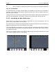
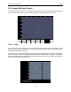
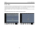
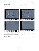
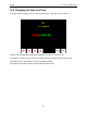
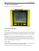
Table Of Contents
- 1 General Overview
- 2 Noggin Components
- 3 Noggin 100 Assembly
- 4 SmartCart Assembly
- 5 SmartTow Assembly
- 6 SmartHandle Assembly (Noggin 500 & 1000 only)
- 7 Rock Noggin Assembly (Noggin 500 & 1000 only)
- 8 Connecting GPS
- 9 Digital Video Logger (DVL)
- 10 Powering Up the System
- 11 Locate & Mark Mode
- 12 Survey & Map Mode
- 12.1 Survey & Map Menu
- 12.2 Data Acquisition
- 12.2.1 Replaying or Overwriting Data
- 12.2.2 Screen Overview
- 12.2.3 Position Information
- 12.2.4 Data Display
- 12.2.5 Section C - Menu
- 12.2.6 Gain
- 12.2.7 Collecting Data using the Odometer
- 12.2.8 Collecting Data in Free Run Mode
- 12.2.9 Collecting Data using the Trigger (or B) Button
- 12.2.10 Noggin Data Screens
- 12.2.11 Calib. (Calibration) Menu
- 12.2.12 Error Messages
- 12.3 Noggin Setup
- 12.4 Noggin File Management
- 12.5 Noggin Utilities
- 13 Troubleshooting
- 14 Care and Maintenance
- Appendix A Noggin Data file Format
- Appendix B Health & Safety Certification
- Appendix C GPR Emissions, Interference and Regulations
- Appendix D Instrument Interference
- Appendix E Safety Around Explosive Devices
- Appendix F Using the PXFER Cable and WinPXFER Software
- F1 Transferring Data to a PC using the PXFER Cable
- F1.1 Connecting the Digital Video Logger to a PC
- F1.2 PXFER Cable Types
- F1.3 Installing and Running the WinPXFER Program
- F1.4 Setting the DVL to the PXFER Cable Type
- F1.5 Transferring Noggin Data Buffer Files
- F1.6 Exporting Nogginplus Data
- F2 Transferring One or More Noggin PCX Files to an External PC using WinPXFER
- Appendix G GPR Glossaries

Noggin 11-Locate & Mark Mode
59
3) Once the depth is matched, save the Soil Type value by pressing the Save button.
11.3.2.3 Soil Moisture
If a good target arch or a target of known depth is not available, the user will have to estimate the
Soil Type. The soil type is most strongly affected by water so the soil type options relate to the
amount of water in the soil.
Change the soil type by pressing the Soil Moisture button until the option that best describes the
soil in the area is displayed. The options are Very Dry, Dry, Moist, Wet and Very Wet Soil.
11.3.3 Identifying Air Wave Reflections
Some arches in the image can be caused by objects that are not in the subsurface, such as
posts, fences, overhead wires and even trees.
An important part of understanding the data image is learning to recognize these unwanted "air"
targets and differentiate them from the targets in the ground.
One way of identifying air reflections is to use the target arch method described above. However,
arches from above-ground objects are wider than objects in the ground and out of the range of
the maximum Soil Type.
Therefore, if the widest Indicator Arch is still not wide enough to match the target arch, the target
arch is from on object in the air, not the ground.