
User's Manual
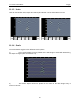
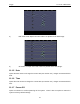

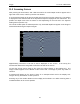
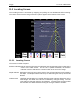
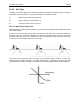
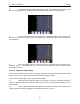
Table Of Contents
- 1 General Overview
- 2 Noggin Components
- 3 Noggin 100 Assembly
- 4 SmartCart Assembly
- 5 SmartTow Assembly
- 6 SmartHandle Assembly (Noggin 500 & 1000 only)
- 7 Rock Noggin Assembly (Noggin 500 & 1000 only)
- 8 Connecting GPS
- 9 Digital Video Logger (DVL)
- 10 Powering Up the System
- 11 Locate & Mark Mode
- 12 Survey & Map Mode
- 12.1 Survey & Map Menu
- 12.2 Data Acquisition
- 12.2.1 Replaying or Overwriting Data
- 12.2.2 Screen Overview
- 12.2.3 Position Information
- 12.2.4 Data Display
- 12.2.5 Section C - Menu
- 12.2.6 Gain
- 12.2.7 Collecting Data using the Odometer
- 12.2.8 Collecting Data in Free Run Mode
- 12.2.9 Collecting Data using the Trigger (or B) Button
- 12.2.10 Noggin Data Screens
- 12.2.11 Calib. (Calibration) Menu
- 12.2.12 Error Messages
- 12.3 Noggin Setup
- 12.4 Noggin File Management
- 12.5 Noggin Utilities
- 13 Troubleshooting
- 14 Care and Maintenance
- Appendix A Noggin Data file Format
- Appendix B Health & Safety Certification
- Appendix C GPR Emissions, Interference and Regulations
- Appendix D Instrument Interference
- Appendix E Safety Around Explosive Devices
- Appendix F Using the PXFER Cable and WinPXFER Software
- F1 Transferring Data to a PC using the PXFER Cable
- F1.1 Connecting the Digital Video Logger to a PC
- F1.2 PXFER Cable Types
- F1.3 Installing and Running the WinPXFER Program
- F1.4 Setting the DVL to the PXFER Cable Type
- F1.5 Transferring Noggin Data Buffer Files
- F1.6 Exporting Nogginplus Data
- F2 Transferring One or More Noggin PCX Files to an External PC using WinPXFER
- Appendix G GPR Glossaries

11-Locate & Mark Mode Noggin
58
4) Press the Soil Type button and toggle through the five different soil types to find
the one that roughly fits the shape of the Indicator Arch to the shape of the Target Arch.
5) Use the Wide and Narrow Arch buttons to change the shape of the Indicator Arch
to match the shape of the Target Arch on the GPR image. The depth of the target is indicated on
the bottom left.
6) Press the Apply button to save the Soil Type and update the Depth Axis on the
Scanning Screen. The Depth axis can now be used to estimate the depth of targets while
scanning in the area.
11.3.2.2 Target at Known Depth
If there are no suitable arches visible in the image to perform the Target Arch Matching described
above, there may be a target of known depth in the area being scanned.
To determine the Soil Type using a target at known depth:
1) With the target response visible on the image, use the Up and Down Arrows to
move the Depth Indicator (and Indicator Arch) until it lies on top of the GPR response of the
known target.
2) Use the Wide and Narrow Arch buttons to change the shape of the Indicator Arch
until the depth of the target, displayed in red above the menu, is correct.