
User's Manual
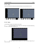
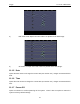

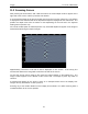
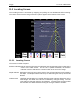
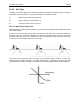
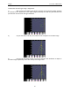
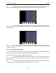
Table Of Contents
- 1 General Overview
- 2 Noggin Components
- 3 Noggin 100 Assembly
- 4 SmartCart Assembly
- 5 SmartTow Assembly
- 6 SmartHandle Assembly (Noggin 500 & 1000 only)
- 7 Rock Noggin Assembly (Noggin 500 & 1000 only)
- 8 Connecting GPS
- 9 Digital Video Logger (DVL)
- 10 Powering Up the System
- 11 Locate & Mark Mode
- 12 Survey & Map Mode
- 12.1 Survey & Map Menu
- 12.2 Data Acquisition
- 12.2.1 Replaying or Overwriting Data
- 12.2.2 Screen Overview
- 12.2.3 Position Information
- 12.2.4 Data Display
- 12.2.5 Section C - Menu
- 12.2.6 Gain
- 12.2.7 Collecting Data using the Odometer
- 12.2.8 Collecting Data in Free Run Mode
- 12.2.9 Collecting Data using the Trigger (or B) Button
- 12.2.10 Noggin Data Screens
- 12.2.11 Calib. (Calibration) Menu
- 12.2.12 Error Messages
- 12.3 Noggin Setup
- 12.4 Noggin File Management
- 12.5 Noggin Utilities
- 13 Troubleshooting
- 14 Care and Maintenance
- Appendix A Noggin Data file Format
- Appendix B Health & Safety Certification
- Appendix C GPR Emissions, Interference and Regulations
- Appendix D Instrument Interference
- Appendix E Safety Around Explosive Devices
- Appendix F Using the PXFER Cable and WinPXFER Software
- F1 Transferring Data to a PC using the PXFER Cable
- F1.1 Connecting the Digital Video Logger to a PC
- F1.2 PXFER Cable Types
- F1.3 Installing and Running the WinPXFER Program
- F1.4 Setting the DVL to the PXFER Cable Type
- F1.5 Transferring Noggin Data Buffer Files
- F1.6 Exporting Nogginplus Data
- F2 Transferring One or More Noggin PCX Files to an External PC using WinPXFER
- Appendix G GPR Glossaries

11-Locate & Mark Mode Noggin
56
11.3.2 Soil Type
To obtain an accurate depth axis and depth estimations of targets in the GPR image, a Soil Type
Calibration must be performed. Soil Type Calibration can be done 3 ways:
1) Matching the shape of a target arch,
2) Using a target at a known depth, or
3) Using the moisture level of the soil.
11.3.2.1 Matching a Target Arch
Targets like pipes, cables, buried artefacts, tree roots and rocks generate arch-shaped responses
on the GPR image.
Arches occur because GPR energy does not travel into the ground as a pencil-thin beam but
more like a 3D cone. Reflections can appear on the record even though the object is not directly
below the GPR sensor. Thus, the GPR sensor "sees" the pipe before and after going over top of
it and forms an arch-shaped response on the image.
Cross long, linear targets like pipes or cables at a 90 degree angle to produce a target arch
suitable for the soil type calibration. The depth estimation of a target will be incorrect if the soil
type calibration is done on a target arch produced at an oblique angle (smaller that 90 degrees).