
User's Manual
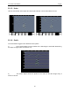
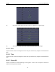
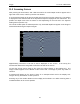
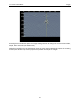
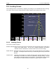
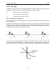
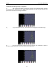
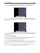
Table Of Contents
- 1 General Overview
- 2 Noggin Components
- 3 Noggin 100 Assembly
- 4 SmartCart Assembly
- 5 SmartTow Assembly
- 6 SmartHandle Assembly (Noggin 500 & 1000 only)
- 7 Rock Noggin Assembly (Noggin 500 & 1000 only)
- 8 Connecting GPS
- 9 Digital Video Logger (DVL)
- 10 Powering Up the System
- 11 Locate & Mark Mode
- 12 Survey & Map Mode
- 12.1 Survey & Map Menu
- 12.2 Data Acquisition
- 12.2.1 Replaying or Overwriting Data
- 12.2.2 Screen Overview
- 12.2.3 Position Information
- 12.2.4 Data Display
- 12.2.5 Section C - Menu
- 12.2.6 Gain
- 12.2.7 Collecting Data using the Odometer
- 12.2.8 Collecting Data in Free Run Mode
- 12.2.9 Collecting Data using the Trigger (or B) Button
- 12.2.10 Noggin Data Screens
- 12.2.11 Calib. (Calibration) Menu
- 12.2.12 Error Messages
- 12.3 Noggin Setup
- 12.4 Noggin File Management
- 12.5 Noggin Utilities
- 13 Troubleshooting
- 14 Care and Maintenance
- Appendix A Noggin Data file Format
- Appendix B Health & Safety Certification
- Appendix C GPR Emissions, Interference and Regulations
- Appendix D Instrument Interference
- Appendix E Safety Around Explosive Devices
- Appendix F Using the PXFER Cable and WinPXFER Software
- F1 Transferring Data to a PC using the PXFER Cable
- F1.1 Connecting the Digital Video Logger to a PC
- F1.2 PXFER Cable Types
- F1.3 Installing and Running the WinPXFER Program
- F1.4 Setting the DVL to the PXFER Cable Type
- F1.5 Transferring Noggin Data Buffer Files
- F1.6 Exporting Nogginplus Data
- F2 Transferring One or More Noggin PCX Files to an External PC using WinPXFER
- Appendix G GPR Glossaries

Noggin 11-Locate & Mark Mode
55
11.3 Locating Screen
The Locating Screen is accessed by stopping and pulling the cart backwards while scanning.
The cursor moves over the image and menu options appear at the bottom of the screen.
11.3.1 Locating Cursor
The Cursor consists of 3 parts:
Position IndicatorVertical cross-hair is tied to the odometer and corresponds to the location at the
center of the GPR sensor. As the cart is pulled backwards, the Position
Indicator moves to indicate the current location of the cart in the image.
Depth Indicator Horizontal cross-hair found at the peak of the soil type indicator arch indicating
the depth. The Depth Indicator moves up or down using the Arch Up and Down
buttons.
Indicator Arch Idealized representation of a typical pipe-like target response observed on the
GPR image. The width of the arch is controlled by soil type setting. The soil
type setting is changed using the Arch buttons. Increasing the soil type makes
the indicator arch wider while decreasing the soil type makes it narrower.