
User's Manual
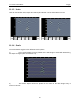
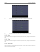

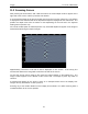
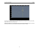
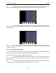
Table Of Contents
- 1 General Overview
- 2 Noggin Components
- 3 Noggin 100 Assembly
- 4 SmartCart Assembly
- 5 SmartTow Assembly
- 6 SmartHandle Assembly (Noggin 500 & 1000 only)
- 7 Rock Noggin Assembly (Noggin 500 & 1000 only)
- 8 Connecting GPS
- 9 Digital Video Logger (DVL)
- 10 Powering Up the System
- 11 Locate & Mark Mode
- 12 Survey & Map Mode
- 12.1 Survey & Map Menu
- 12.2 Data Acquisition
- 12.2.1 Replaying or Overwriting Data
- 12.2.2 Screen Overview
- 12.2.3 Position Information
- 12.2.4 Data Display
- 12.2.5 Section C - Menu
- 12.2.6 Gain
- 12.2.7 Collecting Data using the Odometer
- 12.2.8 Collecting Data in Free Run Mode
- 12.2.9 Collecting Data using the Trigger (or B) Button
- 12.2.10 Noggin Data Screens
- 12.2.11 Calib. (Calibration) Menu
- 12.2.12 Error Messages
- 12.3 Noggin Setup
- 12.4 Noggin File Management
- 12.5 Noggin Utilities
- 13 Troubleshooting
- 14 Care and Maintenance
- Appendix A Noggin Data file Format
- Appendix B Health & Safety Certification
- Appendix C GPR Emissions, Interference and Regulations
- Appendix D Instrument Interference
- Appendix E Safety Around Explosive Devices
- Appendix F Using the PXFER Cable and WinPXFER Software
- F1 Transferring Data to a PC using the PXFER Cable
- F1.1 Connecting the Digital Video Logger to a PC
- F1.2 PXFER Cable Types
- F1.3 Installing and Running the WinPXFER Program
- F1.4 Setting the DVL to the PXFER Cable Type
- F1.5 Transferring Noggin Data Buffer Files
- F1.6 Exporting Nogginplus Data
- F2 Transferring One or More Noggin PCX Files to an External PC using WinPXFER
- Appendix G GPR Glossaries

Noggin 11-Locate & Mark Mode
53
11.2 Scanning Screen
After pressing the Scan button, wait a few seconds for the vertical depth scale to appear on the
right side of the screen, and then push the Cart forward.
A cross-sectional image of the ground scrolls onto the screen from the right to left. The position
is displayed on the horizontal axis at the top while the depth is displayed on the vertical axis. The
position and depth axes units are meters or feet depending on the units set in the Systems
Setting Screen (Section 3.2).
If the Scale or Both option is selected (Section 3.2), horizontal depth lines appear on the image to
assist with determining the depth of targets.
Approximately 16 meters or 50 feet of data is displayed on one screen. If the survey line
exceeds this distance the image will scroll off the left side of the screen.
To save the current screen image to file, press the Camera button on the Display Unit. The
image number appears on the bottom of the screen with a message to press any button to
continue.
A message will appear on the screen if there is no Compact Flash card in the Display Unit.
Images are only saved when a card is present.
Pressing any of the number buttons on the Display Unit marked 1 to 8 while scanning adds a
numbered marker at the current position.