
User's Manual
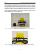
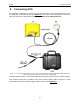
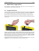
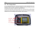
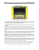
Table Of Contents
- 1 General Overview
- 2 Noggin Components
- 3 Noggin 100 Assembly
- 4 SmartCart Assembly
- 5 SmartTow Assembly
- 6 SmartHandle Assembly (Noggin 500 & 1000 only)
- 7 Rock Noggin Assembly (Noggin 500 & 1000 only)
- 8 Connecting GPS
- 9 Digital Video Logger (DVL)
- 10 Powering Up the System
- 11 Locate & Mark Mode
- 12 Survey & Map Mode
- 12.1 Survey & Map Menu
- 12.2 Data Acquisition
- 12.2.1 Replaying or Overwriting Data
- 12.2.2 Screen Overview
- 12.2.3 Position Information
- 12.2.4 Data Display
- 12.2.5 Section C - Menu
- 12.2.6 Gain
- 12.2.7 Collecting Data using the Odometer
- 12.2.8 Collecting Data in Free Run Mode
- 12.2.9 Collecting Data using the Trigger (or B) Button
- 12.2.10 Noggin Data Screens
- 12.2.11 Calib. (Calibration) Menu
- 12.2.12 Error Messages
- 12.3 Noggin Setup
- 12.4 Noggin File Management
- 12.5 Noggin Utilities
- 13 Troubleshooting
- 14 Care and Maintenance
- Appendix A Noggin Data file Format
- Appendix B Health & Safety Certification
- Appendix C GPR Emissions, Interference and Regulations
- Appendix D Instrument Interference
- Appendix E Safety Around Explosive Devices
- Appendix F Using the PXFER Cable and WinPXFER Software
- F1 Transferring Data to a PC using the PXFER Cable
- F1.1 Connecting the Digital Video Logger to a PC
- F1.2 PXFER Cable Types
- F1.3 Installing and Running the WinPXFER Program
- F1.4 Setting the DVL to the PXFER Cable Type
- F1.5 Transferring Noggin Data Buffer Files
- F1.6 Exporting Nogginplus Data
- F2 Transferring One or More Noggin PCX Files to an External PC using WinPXFER
- Appendix G GPR Glossaries

10-Powering Up the System Noggin
48
A – LOCATE & MARK
B – SURVEY & MAP
1 – CONTACT US
3 - SWITCH MENU
5 – POWER OFF
12.1 V 38°C 02-0181-03??
100°F
• Pressing the A button enters Locate & Mark mode (see Section 11: P.49).
• Pressing the B button enters Survey & Map mode (see Section 12: P.67).
• Pressing the 1 button displays contact information for Sensors & Software Inc.
• Pressing the 3 button switches the menu for use with older Noggin and Noggin
plus
sys-
tems (these are systems with a Yellow or Silver Noggin sticker on top of the electronics
housing). For details on using this menu system, see the Smart Systems manual.
• Pressing the 5 button will turn the DVL off.
This screen also displays the following information:
• Battery Voltage: The system will shut down when the battery voltage reaches about
10.2 Volts (see Section 14.1: P.115 for more details on the battery).
• Temperature: The internal temperature of the DVL is displayed on this screen in Cel-
sius and Fahrenheit.
• Software Version: The version of the software loaded on the DVL.
When the Noggin Smart System is not being used, do not leave the battery plugged in.
The system draws about 0.1 amps even when it is powered off and this will gradually drain
the battery.