
User's Manual
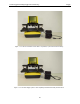
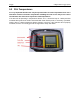
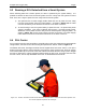
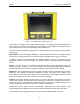
Table Of Contents
- 1 General Overview
- 2 Noggin Components
- 3 Noggin 100 Assembly
- 4 SmartCart Assembly
- 5 SmartTow Assembly
- 6 SmartHandle Assembly (Noggin 500 & 1000 only)
- 7 Rock Noggin Assembly (Noggin 500 & 1000 only)
- 8 Connecting GPS
- 9 Digital Video Logger (DVL)
- 10 Powering Up the System
- 11 Locate & Mark Mode
- 12 Survey & Map Mode
- 12.1 Survey & Map Menu
- 12.2 Data Acquisition
- 12.2.1 Replaying or Overwriting Data
- 12.2.2 Screen Overview
- 12.2.3 Position Information
- 12.2.4 Data Display
- 12.2.5 Section C - Menu
- 12.2.6 Gain
- 12.2.7 Collecting Data using the Odometer
- 12.2.8 Collecting Data in Free Run Mode
- 12.2.9 Collecting Data using the Trigger (or B) Button
- 12.2.10 Noggin Data Screens
- 12.2.11 Calib. (Calibration) Menu
- 12.2.12 Error Messages
- 12.3 Noggin Setup
- 12.4 Noggin File Management
- 12.5 Noggin Utilities
- 13 Troubleshooting
- 14 Care and Maintenance
- Appendix A Noggin Data file Format
- Appendix B Health & Safety Certification
- Appendix C GPR Emissions, Interference and Regulations
- Appendix D Instrument Interference
- Appendix E Safety Around Explosive Devices
- Appendix F Using the PXFER Cable and WinPXFER Software
- F1 Transferring Data to a PC using the PXFER Cable
- F1.1 Connecting the Digital Video Logger to a PC
- F1.2 PXFER Cable Types
- F1.3 Installing and Running the WinPXFER Program
- F1.4 Setting the DVL to the PXFER Cable Type
- F1.5 Transferring Noggin Data Buffer Files
- F1.6 Exporting Nogginplus Data
- F2 Transferring One or More Noggin PCX Files to an External PC using WinPXFER
- Appendix G GPR Glossaries

Noggin 10-Powering Up the System
47
Figure: 10-2 Digital Video Logger (DVL) face
At this stage, the Noggin unit will still be powered down. Once Noggin action is requested (see
later menu items), the DVL will enable power to the Noggin. If the Noggin is receiving power, the
red LED light on the connector to the Noggin will be illuminated.
The water-resistant membrane keypad has a number of buttons that can be pressed to perform
various tasks.
Menu Buttons: The yellow buttons labelled 1 to 8 correspond to menu choices that appear listed
on the screen or along the bottom of the screen when the Digital Video Logger is turned on.
In addition, there are two general-purpose buttons labeled A and B. All buttons are DVL
application dependent and roles change. The operation will be self-explanatory from the display
screen.
Screen: The DVL screen is a grayscale LCD selected for its wide temperature range and
visibility in sunlight. Visibility can be a major problem with viewing GPR data displays outdoors
and considerable effort has been expended on getting a readily visible outdoor display.
Brightness: The yellow Brightness control arrows are used to increase and decrease the screen
brightness. For example, increasing the Brightness setting may improve the visibility of the
screen when in a dark area. Note, however, that increasing the screen brightness also increases
battery consumption so don’t use a bright screen unless necessary.
Contrast: The yellow Contrast control arrows are used to increase and decrease the screen
contrast. For example, increasing the Contrast setting may improve the visibility of the screen on
a bright, sunny day. Increasing the Contrast can also be useful to see weaker features on the
screen. Adjusting the contrast has little effect on battery consumption.
Temperature sensors within the DVL automatically compensate the screen setting so that
manual adjustments of Brightness and Contrast should seldom be needed after initial setup.
Once the Digital Video Logger powers up, the Main Menu is displayed with 4 choices: