
User's Manual
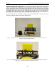
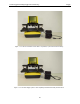
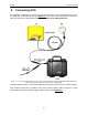
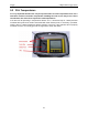
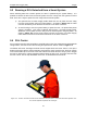
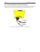
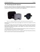
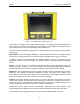
Table Of Contents
- 1 General Overview
- 2 Noggin Components
- 3 Noggin 100 Assembly
- 4 SmartCart Assembly
- 5 SmartTow Assembly
- 6 SmartHandle Assembly (Noggin 500 & 1000 only)
- 7 Rock Noggin Assembly (Noggin 500 & 1000 only)
- 8 Connecting GPS
- 9 Digital Video Logger (DVL)
- 10 Powering Up the System
- 11 Locate & Mark Mode
- 12 Survey & Map Mode
- 12.1 Survey & Map Menu
- 12.2 Data Acquisition
- 12.2.1 Replaying or Overwriting Data
- 12.2.2 Screen Overview
- 12.2.3 Position Information
- 12.2.4 Data Display
- 12.2.5 Section C - Menu
- 12.2.6 Gain
- 12.2.7 Collecting Data using the Odometer
- 12.2.8 Collecting Data in Free Run Mode
- 12.2.9 Collecting Data using the Trigger (or B) Button
- 12.2.10 Noggin Data Screens
- 12.2.11 Calib. (Calibration) Menu
- 12.2.12 Error Messages
- 12.3 Noggin Setup
- 12.4 Noggin File Management
- 12.5 Noggin Utilities
- 13 Troubleshooting
- 14 Care and Maintenance
- Appendix A Noggin Data file Format
- Appendix B Health & Safety Certification
- Appendix C GPR Emissions, Interference and Regulations
- Appendix D Instrument Interference
- Appendix E Safety Around Explosive Devices
- Appendix F Using the PXFER Cable and WinPXFER Software
- F1 Transferring Data to a PC using the PXFER Cable
- F1.1 Connecting the Digital Video Logger to a PC
- F1.2 PXFER Cable Types
- F1.3 Installing and Running the WinPXFER Program
- F1.4 Setting the DVL to the PXFER Cable Type
- F1.5 Transferring Noggin Data Buffer Files
- F1.6 Exporting Nogginplus Data
- F2 Transferring One or More Noggin PCX Files to an External PC using WinPXFER
- Appendix G GPR Glossaries

10-Powering Up the System Noggin
46
10 Powering Up the System
Once all the cable connections are made between the Noggin, the Digital Video Logger (DVL)
and any accessories like odometers and GPS’s, the final step is to connect the system to a 12
volt power source, typically one of the batteries shown in Figure 10-1.
Figure: 10-1 Batteries for Noggin Smart Systems: SmartCart batteries (left) and belt battery (right).
Connect the round 4-pin battery cable on the Noggin-to-DVL cable to the receptacle on the side
of the battery.
The upper red LED light on the DVL panel should be lit. If the battery voltage is low, the light will
flash for about 30 seconds and go out. If the light flashes or does not appear, check the
connections and make sure the battery is fully charged. (See Section 14.1: P.115 for more
information on battery care.)
The voltage indicator can be helpful for identifying when the battery needs to be recharged. If the
battery voltage drops too low the DVL will cease to operate.
The front of the DVL is shown in Figure 10-2. To start the system, press any button on the front
panel. The lower red LED on the front panel should illuminate.